| Gripper Assembly Instructions
Updated 03/01/2010.
Safety first! Wear eye protection and never touch a powered robot!
Note: Do not use Loctite or thread locks on the assembly. They are not necessary and may cause damage to the PVC. Remember that the PVC parts DO have a definite good and a bad side. Try to keep the good sides facing the outside.Â
The PVC panels are laser cut and need to be cleaned before use. Using a damp paper towel, clean the top and bottom while the parts are still attached to the panel, then cut each part from the panel and clean the edges with the paper towel. |
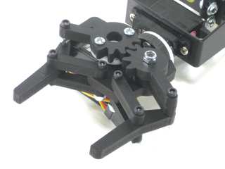
Image of complete gripper. |
| |
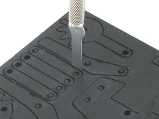
| Removing the parts from the panel
The PVC parts need to be carefully cut out of the panel. A thin, flat blade exacto knife will be very helpful when removing the parts. Simply cut through the tabs to remove the parts. |
Parts in the kit. |
| |
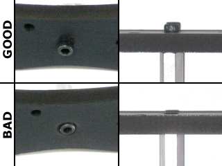
IMPORTANT!
DO NOT overtighten screws on the PVC parts! The PVC will compress and will become weaker as a result! |
Example image. |
| |
Step 1.
Connect the round part and the gripper baseplate together using superglue. |
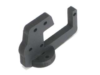
Figure 1. |
|
Step 2.
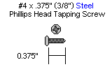
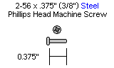
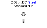
Attach this assembly directly to the wrist rotate servo horn using two #4 x 3/8" tapping screws. If you are not using a wrist rotate assembly, connect directly to the "C" bracket using two 2-56 x .375" machine screws and nuts.
| 2 x (On wrist rotate) |
|
 |
 |
| 2 x (On "C" bracket) |
2 x (On "C" bracket) |
 |
 |
|
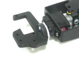
Figure 2. |
| |
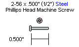
Step 3.
If you are using a heavy duty wrist rotate, then you will need to use two 2-56 x .5" screws instead. Note that you will not need to use the washers as spacers when attaching the new gripper.
| 2 x |
|
 |
|
|
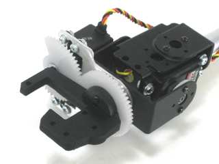
Figure 3. |
| |
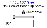
Step 4.
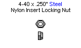
Using two 4-40 x 1" hex head screws, contruct the two fingers for the gripper as shown. Secure with a nylon insert lock nut. DO NOT overtighten this nut. The PVC WILL be damaged.
| 2 x |
2 x |
 |
 |
|
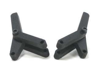
Figure 4. |
| |
Step 5.
Attach the gripper fingers to the gripper base using two 4-40 x 1" hex head screws and nylon insert lock nuts.
| 2 x |
2 x |
|
|
|
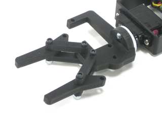
Figure 5. |
|
Step 6.
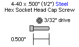
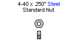
Attach the HS-225 servo to the gripper base with two 4-40 x .5" screws and .250" nuts.
| 2 x |
2 x |
 |
 |
|
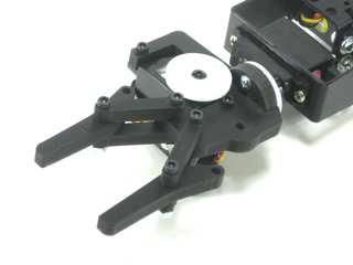
Figure 6. |
| |
Step 7.
Attach a 4-40 x 1" screw to the gripper base as shown with a nylon insert lock nut.
| 1 x |
1 x |
|
|
|
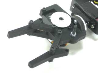
Figure 7. |
|
Step 8.
Slide the passive crossmember spacer over the screw and lock nut. |
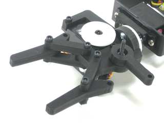
Figure 8. |
| |
Step 9.
Attach the smaller, passive gear part to the assembly as shown. Use a nylon insert lock nut.
| 1 x |
|
|
|
|
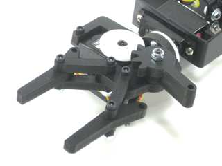
Figure 9. |
| |
Step 10.
Attach the passive gear to the finger assembly using a 4-40 x 1" screw and lock nut as shown.
| 1 x |
1 x |
|
|
|
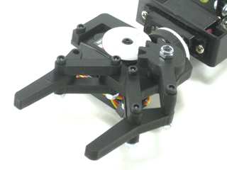
Figure 10. |
|
Step 11.
Make sure that each finger moves freely. They should be tight enough that they do not move out of line, but loose enough so that they can move without resistance. |
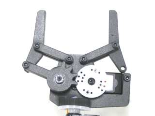
Figure 11. |
|
Step 12.
Insert the 4-40 x .1" Hex head screw through the hole in the larger, driven gear piece as shown. Secure with a nylon insert lock nut.
| 1 x |
1 x |
|
|
|
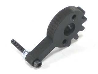
Figure 12. |
| |
| |
Step 13.
Attach this assembly to the gripper finger using a nylon insert lock nut and to the servo horn using two #4 x 3/8" tapping screws.
| 1 x |
2 x |
|
.GIF) |
|
Figure 13. |
| |
Step 14.
Clean the inside of each finger using rubbing alcohol and a paper towel or rag. Apply the foam rubber strips to the inside of the gripper after the surface has dried. |
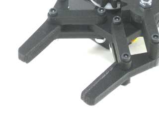
Figure 14. |
| |
Using the Gripper:
The operating principle is simple; Command the servo to close the fingers on the gripper until enough pressure is applied to hold an object. The servo used in this gripper is light weight but also very strong using a metal geartrain. Care must be taken to prevent the servo from being commanded to close too tightly on an object. In this case you must use just enough pressure, but no more than is needed. If the full force is attempted the servo will heat up and self destruct in a short time. |
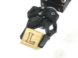
Figure 15. |

.GIF)