Inline Hexapod Body Assembly Instructions Rev. 1
| Inline Hexapod Body Assembly Instructions Rev. 1.
Updated 09/29/2010. Safety first! Wear eye protection and never touch a powered robot! The purpose of this guide is to construct the chassis, attach the legs, and install the electronics. |
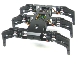 Image of completed Robot. |
||||||
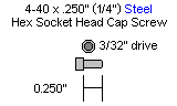
| Step 1.
Build the Body. Use eight 4-40 x 1/4" hex socket screws to attach the spacers to the bottom of the robot.
|
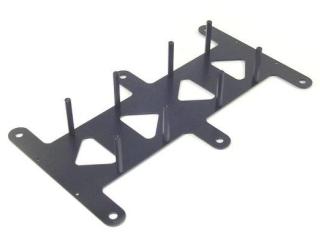 Figure 1. |
||||||
| Step 2. Mount the top of the robot using eight 1/4" hex screws.
|
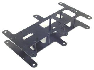 Figure 2. |
||||||
| Step 3. Slide the end panels in as shown, attach using eight 3mm x 6mm screws. Note, it would be a good idea to install the battery into the chassis at this point. Place it in the center of the chassis with the wire closest to the rear of the bot. You can use velcro or double sided tape to hold it in place.
|
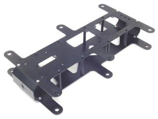 Figure 3. |
||||||
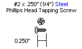
| Step
4. Attach the Legs. Attach the legs as shown, making sure to use right or left legs as indicated. Use twelve #2 x .250" tapping screws.
|
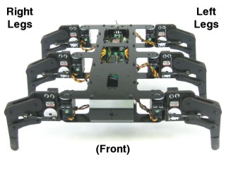 Figure 4. |
||||||
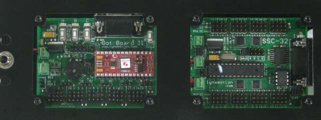
| Step
5. Install the Electronics Install the Atom Pro 28 as shown, taking care not to damage the delicate pins. |
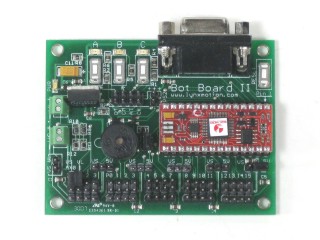 Figure 5-1. |
||||||
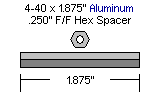
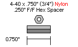
| Step
6. Use four 1/4" hex screws to attach four 3/4" nylon hex spacers to the SSC-32 and Bot Board II as shown.
|
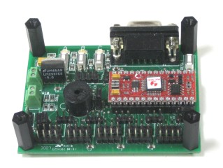 Figure 6-1. |
||||||
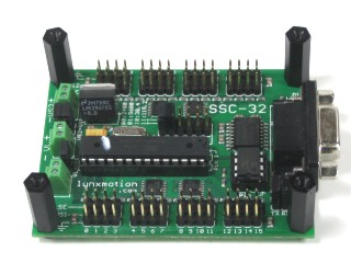 Figure 6-2. |
|||||||
| Step
7. Here are some general guidelines when inserting the wires into the SSC-32 and Bot Board II. Use a 2mm wide flat blade screw driver. Rotate the screw both directions looking into the end of the terminal. When you see it open up, keep turning until it is open completely. Wrap the wires by hand to ensure they are aligned as in Figure 7. Be sure that the wires are fully inserted into the terminals and that no stray wires are able to touch each other as this is a short and can cause the battery to discharge rapidly, causing heat and possibly fire.
|
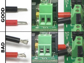 Figure 7. |
||||||
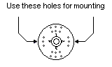
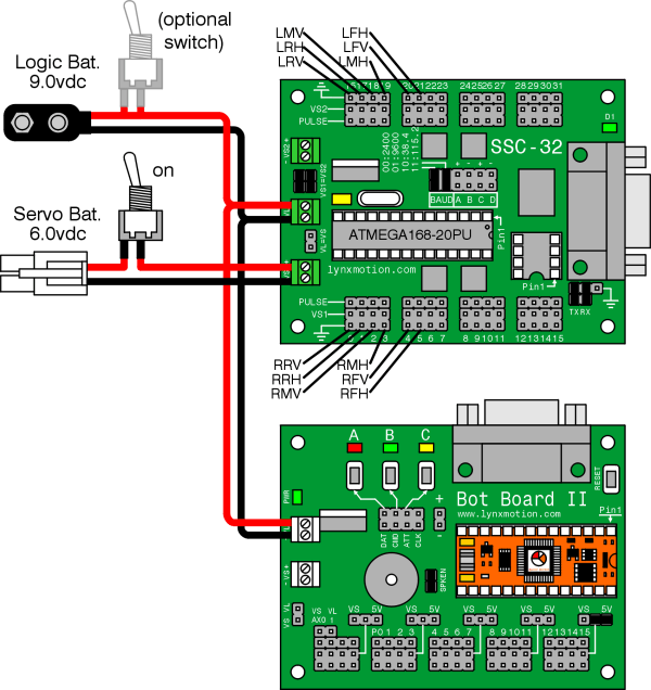
| Step
8. Attach the power cables as shown in Figure 8-1 and in the below schematic. When done, install both boards into the chassis. First, slide the SSC-32 in from the top, orient as shown and attach using four 1/4" hex screws. Connect the loose power cable from the SSC-32's VL terminal to the Bot Board II's VL terminal. Finally, slide the Bot Board II in from the top and secure it using four 1/4" hex screws. You can install the power switch to the robots body in any holes that it will reach.
|
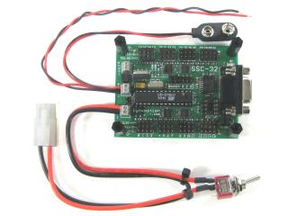 Figure 8-1. |
||||||
|
|
|||||||
|
Schematic.
|
|||||||
| Step
9. Plug the Servos In. Plug the servos into the SSC-32 as illustrated in Figure 9 and the above schematic. Simply plug in the servo associated with the function to the corresponding pin. Be sure the black wire is near the outside of the board and the yellow wire is near the center of the board. |
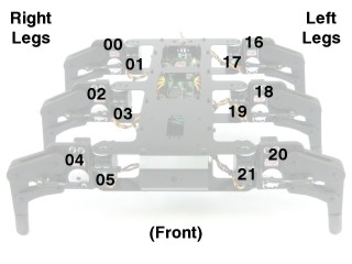 Figure 9. |
||||||
| Step
10. Powering the Robot. Connect a 9v battery to the battery clip to power the electronics. You should see the green LED in the upper right corner of the SSC-32 switch on. There is also a power LED in the upper left corner of the the Bot Board II. If these LEDs do not switch on, immediately power off your robot and double check your connections. Remove the 9v battery from the clip before moving on. |
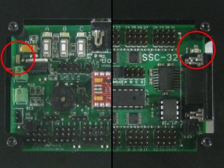 Figure 10. |
||||||
| Step
11. Connect the 6vdc battery pack to the battery harness to power the servos. Flip the switch to turn the servo power on. The LEDs should NOT switch on this time. If they do, immediately power off your robot and double check your connections. Note, our battery packs do NOT come charged. You will need to charge your battery before proceeding to the next tutorial. |
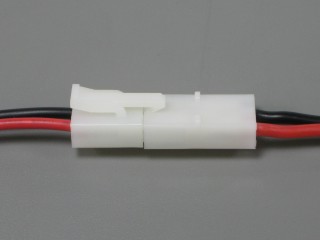 Figure 11. |
||||||