2 DoF B Leg Assembly Instructions
| 2
DOF B Leg Assembly Instructions.
Updated 10/12/2010. Safety first! Wear eye protection and never touch a powered robot! Note: Do not use Loctite or thread locks on the assembly. They are not necessary and may cause damage to the PVC. Remember that the PVC parts DO have a definite good and a bad side. Try to keep the good sides facing the outside. The PVC panels are laser cut and need to be cleaned before use. Using a damp paper towel, clean the top and bottom while the parts are still attached to the panel, then snap each part from the panel and clean the edges with the paper towel. |
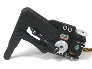
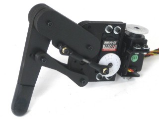 Image of completed Right (robot's right) leg. |
||||
| Step
1. Attach the upper crossmember to the tibia as shown. Note the placement of the "driven" crossmember with the three extra holes. Use caution when tightening the screws. Note, it is possible to over tighten and squish the leg parts if you don't pay attention.
|
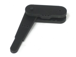 Figure 1-2. |
||||
| Step 2. Attach the lower, passive crossmembers to the tibia as shown.
|
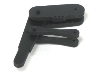 Figure 2. |
||||
| Step
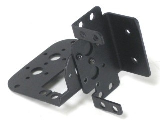
3. Attach the multi purpose bracket to the mechanical advantage bracket, using three 2-56 x .250 screws and 2-56 nuts.
|
|
||||
| Step 4. Take the assembly from step 3 and the PVC part that matches the back of the mechanical advantage bracket and line up the servo hole pattern. Attach the leg's crossmembers to the bracket and PVC as shown.
|
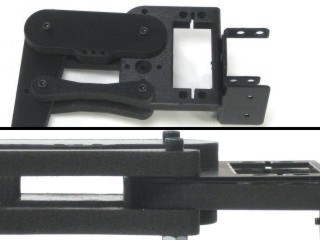 Figure 4-2. |
||||
| Step
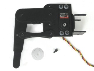
5. Remove the round servo horn and install the servo as shown, using the included 4-40 hardware. Keep the servo horn and screw. You will need them later. |
|
||||
| Step
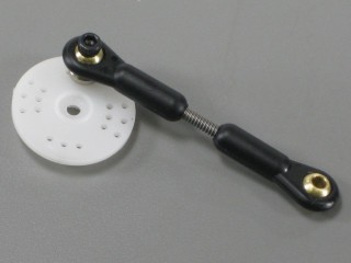
6. Assemble a dog bone using a 1.25" piece of 4-40 threaded rod and a ball link assembly on each end. There should be 3/8" of exposed rod left between them. Alternately, you can make the ball links 2" center to center. Be sure to make all 6 links as close to the same length as possible. |
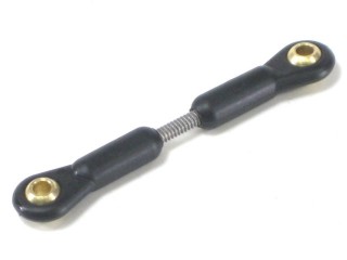 Figure 6. |
||||
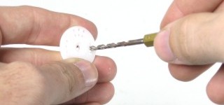
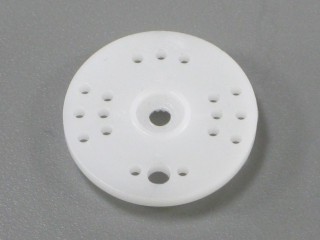
| Step
7. Drill a .125" hole in the servo horn that was removed earlier as shown. This can be done by hand using a drill bit like this.
|
|
||||
| Step
8. Attach the ball link assembly to the servo horn as shown using a 1/2" x 4-40 screw.
|
|
||||
| Step
9. Attach the servo horn to the servo and the other end of the assembly to the driven crossmember using a 3/4" x 4-40 screw. Be sure that the leg is able to reach the two positions shown in Figures 2 and 3.
|
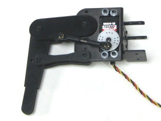 Figure 9-2. |
||||
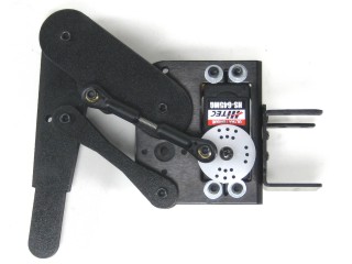 Figure 9-3. |
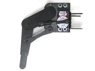 Figure 9-4. |
||||
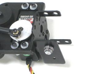
| Step
10. Attach a ball bearing to the bottom of the multi purpose bracket as shown. See the diagram below for detailed information.
|
|
||||
| Step
11. Install the servo as shown, using the included 3mm hardware.
|
|
||||
| Step
12. Slide a rubber end cap over the tibia, and you're finished! |
Figure 12. |
||||