Phoenix Bot Board II / BASIC Atom Pro Tutorial
| Phoenix Bot Board II / BASIC Atom Pro Tutorial.
Updated 08/10/2010. Phoenix code v2.0. Safety first! Wear eye protection and never touch a powered robot! Note: This tutorial applies to the SSC-32 v2 with GP firmware. Software: |
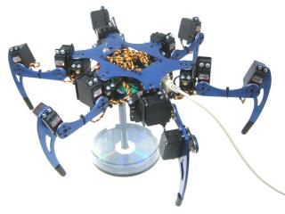
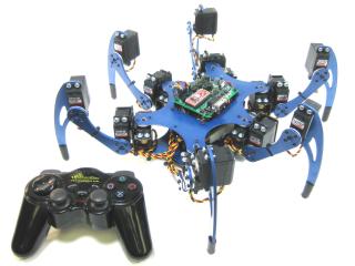 Image of Phoenix. |
||||||||||||||||||||||||||||||||||||||||||||||||||||||||||||||||||||||||||||||||||||
|
I. Phoenix Configuration: SSC-32 Registers |
|||||||||||||||||||||||||||||||||||||||||||||||||||||||||||||||||||||||||||||||||||||
|
Step 1. Download and install LynxTerm. Connect the SSC-32 to the serial port and apply power. The green LED should light and stay on until it receives a valid serial command. Run the LynxTerm program. Please consult the serial troubleshooting guide if you have difficulties with this. |
|
||||||||||||||||||||||||||||||||||||||||||||||||||||||||||||||||||||||||||||||||||||
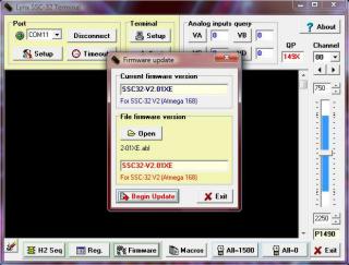
| Step 3. Download the 2.04GP Beta firmware or higher. Remove power from the SSC-32, and make sure the baud rate is set to 115.2k. Refer to the manual if you need more information regarding baud rate. Apply power to the SSC-32 again, make sure it's connected to the PC, and click on "Firmware" along the bottom of the LynxTerm screen. Click on "Open" and browse to the firmware file you just downloaded. Click on "Begin Update". |
|
||||||||||||||||||||||||||||||||||||||||||||||||||||||||||||||||||||||||||||||||||||
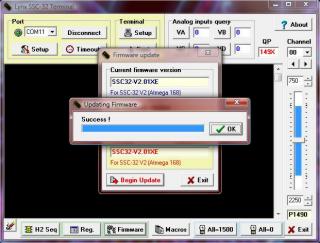
| Step 4. When the firmware has been successfully updated, click "Ok" then "Exit". Now do the "ver" test: type "ver" into the terminal then press "Enter". You should see the proper firmware version returned. |
|
||||||||||||||||||||||||||||||||||||||||||||||||||||||||||||||||||||||||||||||||||||
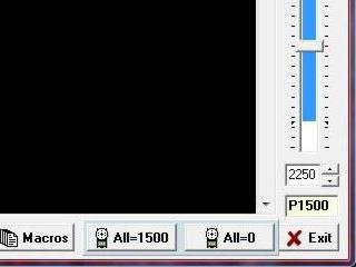
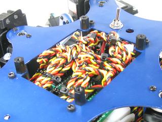
| Step 5. Place the robot in a position as close to neutral as possible. Click on "All=1500" in the bottom right portion of the screen. Your robot should go to and hold the neutral position, and should resemble figures 7, 8, and 9. If the joints are off by more than 15° you may have made an error in assembly. To correct this, remove the center screw from the round servo horn, pull the servo horn off the servo, rotate until it's aligned, then reattach the servo horn. |
|
||||||||||||||||||||||||||||||||||||||||||||||||||||||||||||||||||||||||||||||||||||
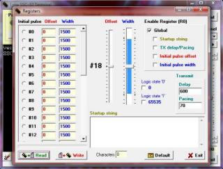
| Step 6. From the main screen, click on "Reg" to open the Registers page. Click on "Default" to initialize default values. |
|
||||||||||||||||||||||||||||||||||||||||||||||||||||||||||||||||||||||||||||||||||||
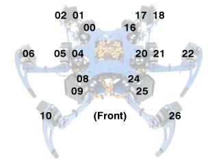
| Refer to this servo channel number guide for the following three steps.
Do the most accurate alignment as possible! The robot can only operate as well as as it is aligned. In other words, a poorly aligned robot will walk poorly! |
|
||||||||||||||||||||||||||||||||||||||||||||||||||||||||||||||||||||||||||||||||||||
| Step 7. You need to adjust the robot's horizontal hip servos. Select servo #0, then adjust the "Offset" slider until the tibia is in line with the horizontal hip servo horn's screws as shown. Do this for servos #00, 04, 08, 16, 20, 24. Note, the mouse's scrollwheel or keyboard's arrow keys can be used to make fine adjustments. |
|
||||||||||||||||||||||||||||||||||||||||||||||||||||||||||||||||||||||||||||||||||||
| Step 8. Now adjust the robot's vertical hip servo. Select servo #1, then adjust the "Offset" slider until the robot's femur is parallel to the ground as shown. Do this for servos #01, 05, 09, 17, 21, 25. |
|
||||||||||||||||||||||||||||||||||||||||||||||||||||||||||||||||||||||||||||||||||||
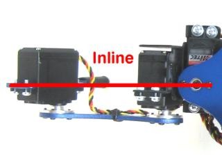
| Step 9. Now adjust the robot's knee servo. Select servo #2, then adjust the "Offset" slider until the tip of the robot's foot is directly underneath the knee servo pivot point. From the servo's pivot point to the tip of the foot should be perpendicular to the ground as shown. Do this for servos #02, 06, 10, 18, 22, 26. |
|
||||||||||||||||||||||||||||||||||||||||||||||||||||||||||||||||||||||||||||||||||||
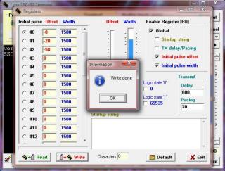
| Step 10. Enable "Initial Pulse Offset", then click "Write" and exit LynxTerm when the write process is finished. Note, you can also check "Initial Pulse Width" to automatically enable the servos on power-up as an option. If you do, make sure you "Write" to save the changes. The next section of this tutorial allows Sequencer to enable the servos instead. This completes the Phoenix configuration process for the SSC-32 registers. Now, whenever the robot is turned on, the servos will automatically be aligned and/or enabled. |
|
||||||||||||||||||||||||||||||||||||||||||||||||||||||||||||||||||||||||||||||||||||
|
II. Phoenix Configuration: Bot Board II Installation |
|||||||||||||||||||||||||||||||||||||||||||||||||||||||||||||||||||||||||||||||||||||
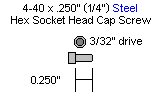
| Step 11. Remove a screw holding the SSC-32's standoffs onto the Phoenix chassis. Replace the screw with the 3/8" M/F standoff as shown. Be careful to not over tighten! Repeat for the remaining three screws. |
|
||||||||||||||||||||||||||||||||||||||||||||||||||||||||||||||||||||||||||||||||||||
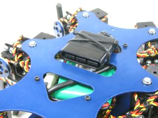
| Step 12. Flip the Phoenix over and attach the PS2 cable's receiver socket as shown. Route the rest of the cable up and out the top.
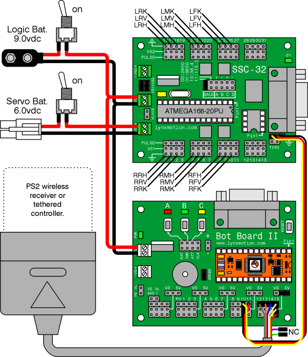
Step 13. Remove the TX and RX jumpers from the lower-right corner of the SSC-32, and plug the unmodified end of the cable in. Yellow on TX, red on RX, and black on ground. Plug in some extra lengths of 18-24awg wires to VL on the SSC-32, with the 9vdc battery clip. These will be used to run power to the Bot Board II. See Tables 14-1 through 14-3, and Schematic 14-3 for connection information. |
|
||||||||||||||||||||||||||||||||||||||||||||||||||||||||||||||||||||||||||||||||||||
|
|
|||||||||||||||||||||||||||||||||||||||||||||||||||||||||||||||||||||||||||||||||||||
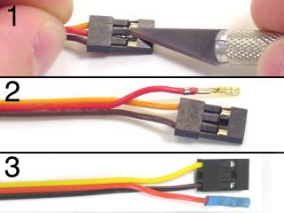
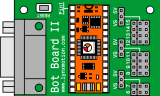
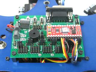
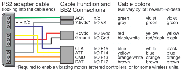
| Step 14. Install the Bot Board II, using 1/4" socket head screws. Plug the modified end of the servo The yellow and black part goes on pin 10 with the black wire toward the outside of the Bot Board II. Plug the red wire in on Pin 11, on the header pin nearest the center of the Bot Board II. Plug in the PS2 cable as shown in Figure 14-2. Plug in the power wires from the SSC-32 to VL. Note: Refer only to Figure 14-2 for connection information. The cable colors in the picture may be outdated. If your cable's colors do not match the diagram, you can find a complete listing of possible colors here. See Tables 14-1 through 14-3, and Schematic 14-3 for connection information. Install the BASIC Atom Pro as shown.
|
|
||||||||||||||||||||||||||||||||||||||||||||||||||||||||||||||||||||||||||||||||||||
|
|
|||||||||||||||||||||||||||||||||||||||||||||||||||||||||||||||||||||||||||||||||||||
|
Connection Information Tables.
|
|||||||||||||||||||||||||||||||||||||||||||||||||||||||||||||||||||||||||||||||||||||
|
Schematic - Figure 14-3. Schematic - Figure 14-3. |
|||||||||||||||||||||||||||||||||||||||||||||||||||||||||||||||||||||||||||||||||||||
| Step 15. Download the Basic Micro Studio from (here). Install and run the IDE to allow programming the chip. Connect the serial data cable to the PC's serial port. This can be recognized by having 9 pins that stick out. Connect the other end of the serial data cable to the Bot Board's DB9 port. Note, you can also use a BAFO BF-810 or IOGear USB-to-Serial adaptor. |
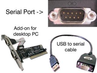 Figure 15. |
||||||||||||||||||||||||||||||||||||||||||||||||||||||||||||||||||||||||||||||||||||
| For
Phoenix or CH3-R with PS2 controller:
Step 16. Download the Program Note: The software switches the controller to analog mode. However, some controllers may need to be put into analog mode manually. If you hear a continuous beeping, the PS2 controller is not connected to the Atom properly or is not functioning. If you hear beeping, you can try pressing Reset on the Bot Board II. You can also test the controller with a Playstation 2 to verify that it is working. |
|
||||||||||||||||||||||||||||||||||||||||||||||||||||||||||||||||||||||||||||||||||||
| Step 17. Controlling the
Robot with PS2 Controller The default is Walking mode 1. Use the Left joystick to move the robot around without turning (this is called "translation"), and the Right joystick rotates the robot as it moves. Up and Down on the D-Pad increases or decreases the height of the body. The Triangle button puts the body at 35mm from the ground. The Circle button puts the body onto the floor in a 'resting' position. Press Triangle or Up on the D-Pad to raise the body. There are four special "body moves" functions that are triggered by pressing L1, L2, Circle, or X. While in one of these modes, the hexapod does not walk. The joysticks and some buttons change function depending on which mode is toggled on; see Table 17 for details. |
|||||||||||||||||||||||||||||||||||||||||||||||||||||||||||||||||||||||||||||||||||||
|
PS2 Controls
Table 17. |
|||||||||||||||||||||||||||||||||||||||||||||||||||||||||||||||||||||||||||||||||||||
| For
Phoenix or CH3-R with DIY controller:
Information on the DIY controller is located on our forum. Step
18. Download the Program |
|
||||||||||||||||||||||||||||||||||||||||||||||||||||||||||||||||||||||||||||||||||||
| Step
19. Controlling the
Robot with DIY Controller Use the Left joystick to control the body height and rotation. The Right joystick handles walking and strafing. There are four special "body moves" functions that are triggered by pressing B, C, or D. While in one of these modes, the hexapod does not walk. The joysticks and some buttons change function depending on which mode is turned on; see Table 19 for details. Press A to go back to normal Walking mode. |
|||||||||||||||||||||||||||||||||||||||||||||||||||||||||||||||||||||||||||||||||||||
|
DIY Controls
Table 19. |
|||||||||||||||||||||||||||||||||||||||||||||||||||||||||||||||||||||||||||||||||||||