AL5D Arm Assembly Instructions Rev. 2.1
| AL5D Arm Assembly Instructions Rev. 2.1.
Updated Dec 2014 Safety first! Wear eye protection and never touch a powered robot! This guide shows how to assemble the AL5D arm with either the SSC-32 or the SSC-32U servo controller. Take note of which version you have and follow each step accordingly, as the connections and configuration are different. Calibration of the arm is done using one of the following software:
Note: Loctite / thread lock can be used on the construction of the aluminum components, though it is not necessary if the nuts are properly tightened. However, don't use them with Lexan or plastic, as they are not necessary and may cause damage. |
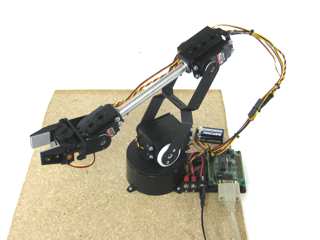 Image of complete arm (SSC-32 shown). |
|||||||||||||||||||||||
| Lexan Preparation. The lexan pieces have a protective covering that needs to be removed before assembly. When the laser cuts, the covering melts into the cut edge which can make removal difficult. If you gently scrape the cut edge with a flat blade screwdriver, the covering can easily be lifted and peeled off. On smaller pieces the coverings can be more difficult to remove. If you have trouble you can gently scrape the cut edge, then use duct tape to lift the covering off. For further information on lexan, see this page. |
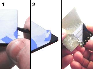 Lexan Preparation. |
|||||||||||||||||||||||
|
Step 1.
|
 Figure 1. |
|||||||||||||||||||||||
| Step 2. Install the mechanical dampening panels as shown. Use four 2-56 x 1/4 inch machine screws. Be sure to add the discs to the correct side and ensure the protective covering has been removed from the Lexan parts. Press down when screwing to ensure there is no gap between the Lexan and the aluminum, as the screw will be threading the Lexan.
|
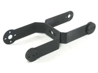 Figure 2. |
|||||||||||||||||||||||
|
Step 3.
|
 Figure 3. |
|||||||||||||||||||||||
|
Step 4. Caution - don't over-tighten this! If the arm is operated with the mechanical dampeners too tight, the servo WILL heat up and CAN be damaged!
|
 Figure 4. |
|||||||||||||||||||||||
|
Step 5.
|
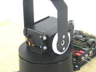 Figure 5. |
|||||||||||||||||||||||
|
Step 6.
|
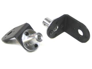 Figure 6. |
|||||||||||||||||||||||
|
Step 7.
|
.jpg) Figure 7. |
|||||||||||||||||||||||
|
Step 8.
|
.jpg) Figure 8. |
|||||||||||||||||||||||
|
Step 9.
|
 Figure 9. |
|||||||||||||||||||||||
|
Step 10. Caution - don't over-tighten this! If the arm is operated with the mechanical dampeners too tight, the servo WILL heat up and CAN be damaged!
|
 Figure 10. |
|||||||||||||||||||||||
| Step 11. Figure 5 show a typical mega-size servo with its default servo horn at center position. You will need to replace this black servo horn with the round nylon servo horn. Remove the servo horn screw, being careful to not rotate the servo horn itself. Pull the servo horn off, then press the nylon servo horn in place, as close to the alignment shown as possible. Replace the servo horn screw. Make sure your servo looks like the image. The arrows in the image point to the screw holes you will use. |
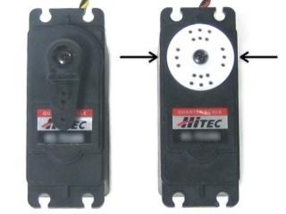 Figure 11. |
|||||||||||||||||||||||
| Step 12. Attach the HS-755HB elbow servo to the bracket as shown using the 3mm hardware; follow the diagram below. Use two #2 x 1/4" tapping screws to secure the bracket to the servo horn. Route the shoulder servo wires over the servo. Plug the servo into channel 2 on the SSC-32.
|
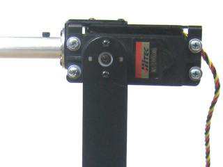 Figure 12. |
|||||||||||||||||||||||
| Step
13. Attach the Little Gripper connector to the short "C" bracket using two 2-56 x .250" screws and 2-56 nuts. |
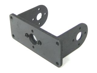 Figure 13. |
|||||||||||||||||||||||
| Step 14. Attach the short "C" bracket to the other Multi-purpose bracket as shown.
|
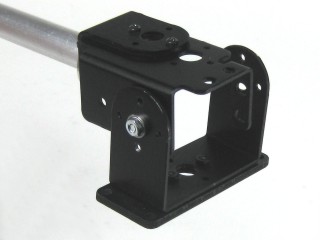 Figure 14. |
|||||||||||||||||||||||
| Step
15. Figure 15 illustrates a typical standard-size servo with its output horn (the round white part) at center position. Make sure your servo looks like the image. The arrows in the image point to the screw holes you will use. |
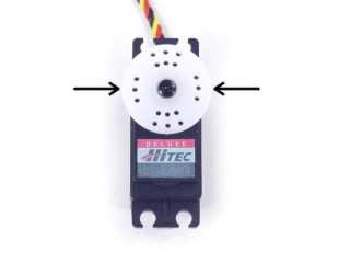 Figure 15. |
|||||||||||||||||||||||
|
Step 16.
|
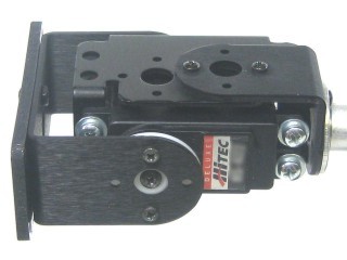 Figure 16. |
|||||||||||||||||||||||
| Step 17. Add a 6" servo extender cable to the elbow servo. Plug the cable in to channel 2 on the SSC-32. Note that the colors should remain the same on both sides of the connection (yellow to yellow, red to red, black to black). |
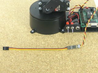 Figure 17. |
|||||||||||||||||||||||
| Step 18. Attach the Little Grip to the lexan as shown, using three 4-40 x .375" button head screws and acorn locking nuts. Only three screws are used (shown in the image) as the body of the gripper servo is in the way for the fourth. Make sure the HS-422 (a HS-322HD
may be substituted) servo is aligned to mid-position, and the gripper
is halfway open. Now the servo and gripper will be aligned correctly.
Remove the servo screw and horn. Slide the servo into the gripper from
the bottom. You may need to wiggle it, just a little bit, to get it
seated properly.
Use the servo screw to attach the servo. Tighten this down, but then
unscrew it half a turn. Too much friction can bind the servo.
Step 19. |
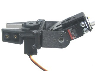 Figure 18. |
|||||||||||||||||||||||
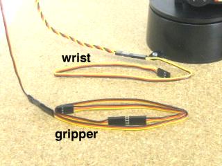 Figure 19. |
||||||||||||||||||||||||
| Step 20. Carefully bend the wrist servo back as far as it will go, and use wire ties to secure the servo cables as shown. Make sure to leave slack in the gripper servo cable, don't pull it too tight. |
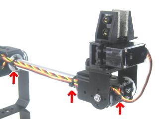 Figure 20. |
|||||||||||||||||||||||
|
Step 21.
|
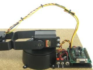 Figure 21 (SSC-32 shown). |
|||||||||||||||||||||||
| Step 22a (SSC-32 / Lynxterm). If you have the SSC-32U (USB connector), please proceed with Step 22b. If you have the SSC-32 (serial connector), we'll use LynxTerm to test the servos and confirm that they're all plugged into the proper channels (just as in the Base Assembly Instructions). If you have not done so before, download and install LynxTerm. Connect the SSC-32 to the serial port and apply power. The green LED should light up and stay on until it receives a valid serial command. Run the LynxTerm program. If LynxTerm cannot connect, please consult the serial and USB-to-serial troubleshooting guide. Now test the servos and connections by selecting a channel, and moving the servo carefully using the slider bar. Verify that the servos are plugged into the channels as listed in Table 21. Easy does it; this is real time control, so be careful! Select channels 0 through 4 one at a time and test that each works.
|
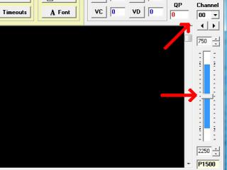 Figure 22a (Lynxterm). Figure 22a (Lynxterm). |
|||||||||||||||||||||||
| Step
22b (SSC-32U / Servo Utility). Just like in the base instructions, we will use the SSC-32 Servo Sequencer Utility to test the servos and confirm they are all plugged into their proper servo channels and oriented correctly. If not done so before, download and install the SSC-32 Servo Sequencer Utility. Connect the USB cable and power the board using the on/off switch. Run the program. The SSC-32U is shipped with a baud rate of 9600. Ensure the baud rate towards the bottom right of the window is set to 9600 (not 115200). The software should automatically detect which COM port is connected to the SSC-32U, and have installed the FTDI (USB to serial) drivers automatically. Ensure Servos 0 4 are checked off in the software (and therefore accessible). You can now move the sliders to see each servo rotate. Verify that the servos are plugged into the channels as listed in Table 21. Easy does it; this is real time control, so be careful. For more information, please consult the SSC-32 Servo Sequencer Utility manual. |
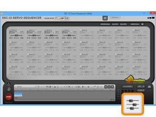 Figure 22b (SSC-32 Utility). |
|||||||||||||||||||||||
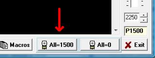
| Step 23a (SSC-32 / Lynxterm). Click on the "All = 1500" button in LynxTerm. This will command the servos to hold center position. Your arm should look like Figure 24. If any joint is off by more than 15°, then you may have made an error in assembly. If you did not purchase RIOS software, please proceed to step 28.
|
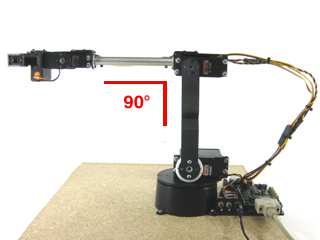 Figure 23. |
|||||||||||||||||||||||
| Step
23b (SSC-32U / Servo Utility). Click on the "Calibrate" button in the SSC-32 Servo Sequencer Utility. A knob next to each servo will appear (figure 23b). This knob is used to fine tune the servo's center position. The knob is not intended to be rotated: click the knob you wish to rotate, keeping the mouse button down, and drag up and down to rotate the knob. Do this for each servo until the arm looks like figure 23, and angles are 90 and 180 degrees. If any joint is off by more than 15°, then you may have made an error in assembly. Once all servos have been properly positioned, click the "calibrate" button again to exit calibration mode. The offsets will automatically be saved on the SSC-32 / SSC-32U. If you did not purchase the RIOS software, please proceed to step 28. |
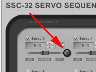 Figure 23b (SSC-32 Utilty). |
|||||||||||||||||||||||
| Step 24 (RIOS Users Only). Should you have purchase RIOS, or a version of the arm which includes RIOS, please follow the next steps. To use the RIOS Arm control software, you need to make one minor modification. Remove the servo horn screw from the elbow servo. Pull the servo horn off the servo, lift the arm two 'clicks' (30°) at the elbow and reattach the servo horn and screw. Note, the Hitec spline has 24 grooves, so each groove is 15°. |
 Figure 24. |
|||||||||||||||||||||||
| Step 25 (RIOS
Users Only). At this point the arm is assembled and tested using LynxTerm. Now we need to install RIOS and calibrate the arm to the software. Use the RIOS Help File to calibrate and use the arm. Install RIOS, following the on-screen installation prompts. The serial number is on the back of the CD sleeve. Use the RIOS Help File to calibrate and use the arm, following Steps 1-7. When you get to Step 8 in the help file, please use the following instructions instead. Please take the time to do an accurate calibration. The performance of the arm will only be as good as the calibration. If the on screen virtual arm does not match the real arm this is a sign of an inaccurate calibration. After calibration please study the RIOS manual carefully to learn how to store and playback sequences for the arm. |
|
|||||||||||||||||||||||
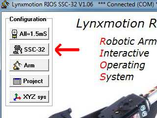
| Step 26 (RIOS
Users Only). To calibrate the arm's Shoulder servo, click the "SSC-32" button. |
|
|||||||||||||||||||||||
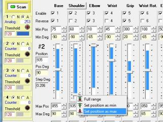
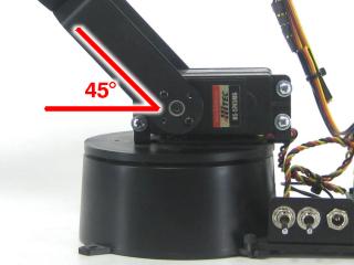
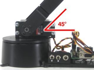
| Step 27 (RIOS
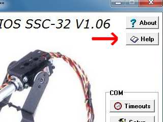
Users Only). Start the servo configuration with the Shoulder, servo #2. Move the shoulder slider up to move the shoulder forward so that it looks like Figure 28-2. Set the Min Deg angle -45°. Right click on the slider to set this as the Min Position. Now the servo will not go past this value, and the program now knows this value is exactly 45° from centered. Now move the slider down to move the shoulder backward so that it looks like Figure 28-3. Set the Max Deg angle to 45°. Right click on the slider to set this as the Max Position. Now the servo will not go past this value, and the program now knows this value is exactly 45° from centered. The next step is to read and study the RIOS users guide. It is accessible by clicking on the help icon on the main screen or by navigating to the install directory (c:\Program Files\RIOS_SSC-32\) and opening the Help.pdf file. This manual explains in great detail how to use the arm. |
|
|||||||||||||||||||||||
|
|
|
|||||||||||||||||||||||
| Step 28. To connect springs for load-balancing, replace the servo attachment hardware in the locations shown, following the diagrams below. Hook the springs together after they're secured.
|
 Figure 28. |
|||||||||||||||||||||||
| Step 29. The arm assembly is complete. The arm is robust mechanically, but the servos can be damaged by improper use. An example would be if the arm was told to move to an unobtainable position, like the surface the arm is mounted to, or by crashing into itself or other objects. The elbow servo is the most vulnerable because it holds the entire weight of the forearm. As indicated in step 28, load balancing springs should be added to reduce some of this load. If you purchased FlowBotics Studio, FlowStone or FlowArm, you can proceed with the instruction guide(s) associated with those programs. People do not like holding heavy objects with their arms outstretched in front of them. Servo based robot arms don't like it much either. Remember, the most important rule for servo based robot arms: Park the arm when not in motion! When it's moving or at rest it's usually ok. When it's holding an object it should do so for the minimum amount of time required to do the job. You can always touch the servo case to see if it's getting hot. |
||||||||||||||||||||||||