
RC Digital Servo End Stops (HFP-10)
| Programming
Digital Servos' End Stops with the HFP-10.
Updated 04/18/2006. |
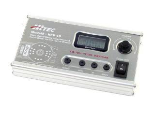 Image of Servo Programmer. |
| Step
1. The first step in using the Hitec Digital Servo Programmer is providing power. The programmer was designed for setting up servos for use in high-end equipment such as RC helicopters and planes. Because of this, Hitec assumes the user already owns one of their remote control units, which includes a compatible charger. Since most robot enthusiasts don't have an RC radio system, an alternate method of powering the unit is required. The battery that is included is a NiCd 4-cell pack. If you have a way of charging this pack, then proceed to Step 2. If not, follow these steps to provide an alternate power source. Remove the left side panel and remove the NiCd battery pack. There is a red (+) and a black (-) wire inside and all you need to do is connect a 4-cell AA battery holder or our battery quick connect with our 5-cell NiMH pack. |
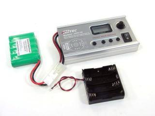 Figure 1. |
| Step
2. The programmer is capable of changing many of the servo's parameters, but we are only interested in changing the end stops in this tutorial. The menu system uses "UP/L" and "DN/R" to scroll through the options. "INPUT" is used as enter. |
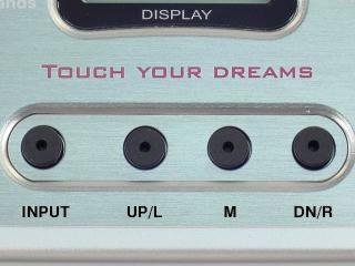 Figure 2. |
| Step
3. Connect a servo to the port on the upper right. Turn the unit on and press "UP/L" until you see "->Program EPAneuFS". Then press "INPUT". |
 Figure 3. |
| Step
4. If you see an arrow (see Figure 4), you must rotate the "ADJUST" knob slowly in the direction indicated until you see two arrows. At this time, the programmer enables the servo and displays the actual position. |
 Figure 4. |
| Step
5. Rotate the "ADJUST" knob counter-clockwise slowly until "-200" is displayed. Then press "UP/L". This programs the CCW end point to -90°. |
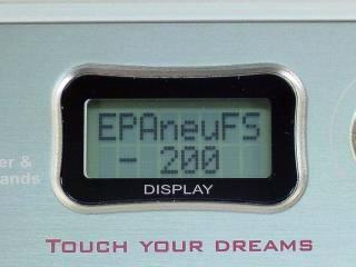 Figure 5. |
| Step
6. Rotate the "ADJUST" knob clockwise slowly until "+200" is displayed. Then press "DN/R". This programs the CW end point to 90°. This completes the process of changing the servo from 90° of range to 180° of range. Press "INPUT" now to exit. This prevents changing the Neutral and Fail Safe settings. |
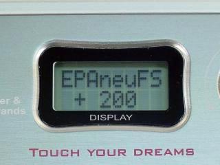 Figure 6. |
| Step
7. To test your servo, press "UP/L" until you see "->S-Test Manual", then press "INPUT". |
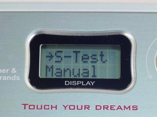 Figure 7. |
| Step
8. Rotate the "ADJUST" knob until "1500 uS" is displayed. At this point, the servo's output shaft should be centered. Rotate the "ADJUST" knob until "900 uS" is displayed. The servo's output shaft should be -90° (counter-clockwise from center). Rotate the "ADJUST" knob until "2100 uS" is displayed. The servo's output shaft should be +90° (clockwise from center). You can now remove the servo from the programmer. |
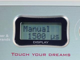 Figure 8. |