
Humanoid Biped Leg Pair Assembly Guide
| Humanoid Biped Leg Pair Assembly Guide. Updated 08/30/2007
Hardware: Goal: Notes: |
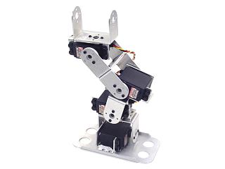 Image of Humanoid Biped's Right Leg. |
| Step 1. Attach a multi-purpose servo bracket to a "C" bracket as shown, using two 2-56 x .250" screws and 2-56 nuts. 2 x |
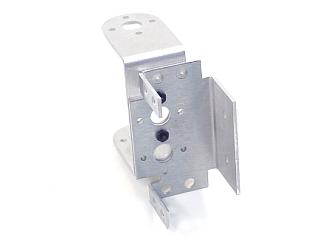 Figure 1. |
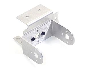
| Step 2. Attach two "C" brackets as shown, using two 2-56 x .250 screws and 2-56 nuts. 2 x |
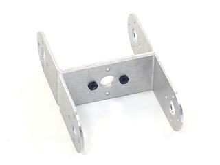 Figure 2. |
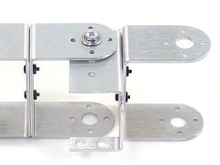
| Step 3. Connect the "C" bracket to the multi-purpose bracket as shown. See figure 3-1 for detailed information.
|
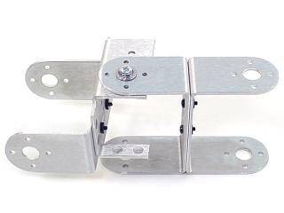 Figure 3-2. |
| Step 4. Attach a multi-purpose servo bracket to a "C" bracket as shown, using two 2-56 x .250" screws and 2-56 nuts. 2 x |
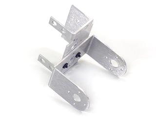 Figure 4. |
| Step 5. Connect the "C" bracket to a multi-purpose bracket as shown. See figure 5-1 for detailed information.
|
|
| Step 6. Attach a multi-purpose servo bracket to a "C" bracket as shown, using two 2-56 x .250" screws and 2-56 nuts. 2 x |
|
| Step 7. Connect the "C" bracket to a multi-purpose bracket as shown. See figure 7-1 for detailed information.
|
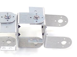 Figure 7-2. |
| Step 8. Attach a multi-purpose servo bracket to the foot panel as shown, using three 2-56 x .125" screws and 2-56 nuts. 3 x |
|
| Step 9. Connect the "C" bracket to a multi-purpose bracket as shown. See figure 9-1 for detailed information.
|
|
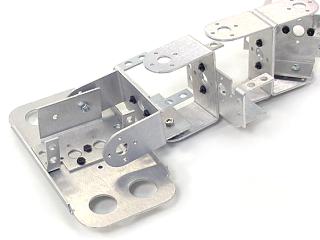
| Step 10. Attach the servos as shown, using the included 3mm hardware, and two #2 tapping screws. For quick prototype assembly, you can use rivet fasteners (sold separately: NSRF-01) as illustrated. 16 x |
Figure 10. |
| Step 11. When you are ready to attach the legs to your biped torso, attach the "C" brackets as shown, using the ball bearing hardware and four #2 tapping screws. 2 x |
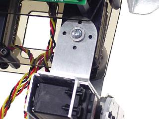 Figure 11. |
 2 x
2 x 
 3 x
3 x 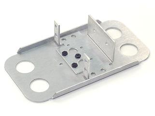
 8 x
8 x 
 4 x
4 x