The Complete H3/H3-R Tutorial (Bot Board II) v2.0
| The Complete H3/H3-R Tutorial
v2.0
Updated 02/08/2012 This guide applies to the Bot Board II. The purpose of this guide is to use the Hexapod Calibration program to calibrate the servos and to program the Basic Atom Pro 28 for PS2 remote control. Note, we used the round hexapod for the images in the tutorial, however, everything still applies to the inline hexapod. Note, the PS2 control programs have been verified to work with our Lynxmotion wireless controllers. We cannot guarantee that non-Lynxmotion controllers will work. Hardware: Software: |
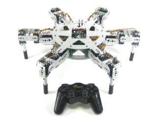 Image of AH3-R. |
||||||||||||||||||||||||||||||||||||||||||||||||||||||||||||
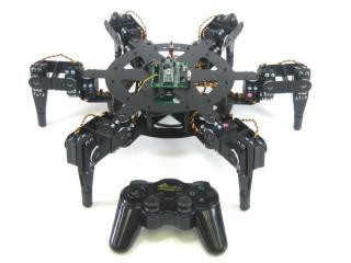 Image of BH3-R. |
|||||||||||||||||||||||||||||||||||||||||||||||||||||||||||||
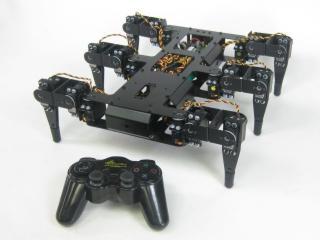 Image of BH3. |
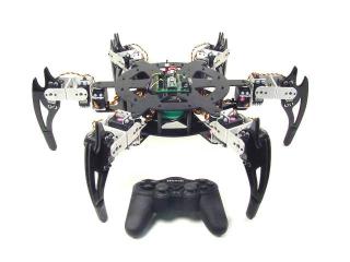 Image of CH3-R. |
||||||||||||||||||||||||||||||||||||||||||||||||||||||||||||
|
|
|||||||||||||||||||||||||||||||||||||||||||||||||||||||||||||
| Step 1. The first thing you need to do is use the Hexapod Calibration program to calibrate the robot's legs. Download the program here. Just unzip the zip file and run the installer. This will automatically create an icon on your desktop so you can easily run it. |
 Figure 1. |
||||||||||||||||||||||||||||||||||||||||||||||||||||||||||||
| |
|||||||||||||||||||||||||||||||||||||||||||||||||||||||||||||
| Step 2. Connect the serial data cable to the PC's serial port. This can be recognized by having 9 pins that stick out. Note, the USB to Serial adapter cable on our website is guaranteed to work with our robots. However, we cannot guarantee that other brands or models will communicate quickly enough to function properly. Please consult the serial troubleshooting guide if you have difficulties with this. |
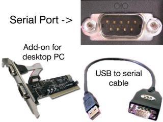 Figure 2. |
||||||||||||||||||||||||||||||||||||||||||||||||||||||||||||
| Step 3. Set the robot up on a stand such as a CD spindle. Connect the DB9 or USB-to-serial cable to your PC and to the SSC-32. Power up the robot. Verify that the green LED on the SSC-32 lights up. Note, this is NOT a power indicator. Its purpose is to light up, indicating that the SSC-32 is functioning properly. It will remain lit until it receives serial data. After that, it will blink when receiving data. The servos may jump but will not hold position yet. |
|||||||||||||||||||||||||||||||||||||||||||||||||||||||||||||
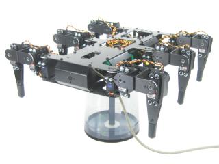 Figure 3-1. |
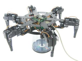 Figure 3-2. |
||||||||||||||||||||||||||||||||||||||||||||||||||||||||||||
Step 4. Click "All=1500" to enable the servos. The robot's legs should move quickly into position as in Figures 3-1 or 3-2, and should hold this position. If the legs move into position but suddenly go limp, this is an indication of a low battery. A low battery can't deliver the required current, causing the SSC-32 to reset. Another clue that this is happening is the SSC-32's green LED will be on steady, as it is upon powerup. If the legs are holding position but look radically different, then a mistake may have been made in the assembly. To correct this, you can remove the center servo horn screw, pull the servo horn off the servo, reposition it, and press it back on the servo. Then replace the servo horn screw. Don't worry if the legs are off a little bit (under 15°) as this will be corrected in the servo offset procedure. Note, you can click on "inline" if you do not have a circular chassis for a more accurate visual representation. |
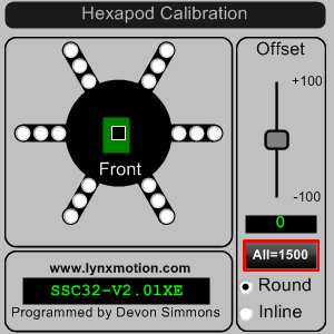 Figure 4. |
||||||||||||||||||||||||||||||||||||||||||||||||||||||||||||
| Step 5. We will now begin to use the servo offset adjustment to fine-tune the alignment of the leg joints. The goal is to align the leg to be perpendicular to the chassis and for the knee to form a perfect right angle. (See Figures 5-1 and 5-2.) We are assuming that you have your servos plugged into the appropriate pins, according to the assembly guide. Select a hip servo by clicking on the corresponding radio button. Move the Offset slider around until the joint is aligned. You can move it using the scroll wheel or arrow keys for fine tuning. After aligning the hip servo, move on to the next closest servo to the body. Finally adjusting the knee servo last. Align the rest of the robot's legs in this manner. When you move to another servo, the previous one is marked as red to show your progress.
|
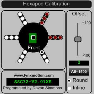 Figure 5. |
||||||||||||||||||||||||||||||||||||||||||||||||||||||||||||
| |
|||||||||||||||||||||||||||||||||||||||||||||||||||||||||||||
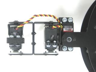 Figure 5-1. |
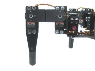 Figure 5-2. |
||||||||||||||||||||||||||||||||||||||||||||||||||||||||||||
| Step 6. We're now done communicating with the SSC-32 from a PC, so we need to change the settings to communicate with the Basic Atom Pro 28. Remove the DB9-enable jumpers and install the DC-01 with the narrow (0.1") spaced connector on the TTL serial communication posts. The black wire is closest to the edge of the board, and the yellow wire is on RX. See the schematic below for detailed information. |
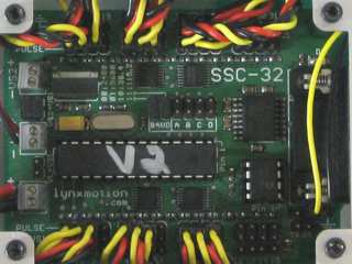 Figure 6. |
||||||||||||||||||||||||||||||||||||||||||||||||||||||||||||
| Step 7. For the round chassis, remove the 3/8 x 4-40 screws that hold the SSC-32 in place. Install the Bot Board as illustrated in Figure 7 using the same screws. Attach the red and black wires from the SSC-32 to the VL input, with black on (-) and red on (+). For both chassis styles, make sure that the ABC buttons / LED jumpers are removed. Install the speaker enable jumper. Install the DC-01 to I/O P8, where black is closest to the outside of the board and yellow is on the I/O pin. Consult the manual for the Bot Board II if needed. See the schematic below for detailed information. |
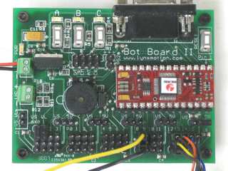 Figure 7. |
||||||||||||||||||||||||||||||||||||||||||||||||||||||||||||
| Step 8. Install the Playstation 2 cable as illustrated in Figure 8-1. Note: Refer only to Figure 8-1 for connection information. The cable colors in the picture may be outdated. If your cable's colors do not match the diagram, you can find a complete listing of possible colors here.
|
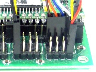 Figure 8-2. |
||||||||||||||||||||||||||||||||||||||||||||||||||||||||||||
Schematic.
|
|||||||||||||||||||||||||||||||||||||||||||||||||||||||||||||
| Step 9. Use some double-sided foam tape to stick the PS2 cable on the bottom of the robot as shown. This will make it easier to swap controllers if needed. |
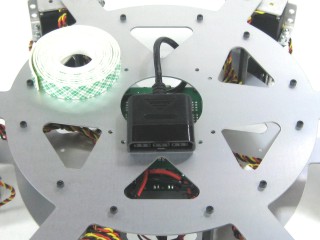 Figure 9. |
||||||||||||||||||||||||||||||||||||||||||||||||||||||||||||
| Step 10. Download the Program Download BASIC Micro Studio from. Install and run the program to allow programming the chip. Please consult the serial troubleshooting guide if you have difficulties with this. Select the proper code for your robot from the table below.
|
 Figure 10. |
||||||||||||||||||||||||||||||||||||||||||||||||||||||||||||
| Step 11. Controlling the Robot Make sure your PS2 controller is turned on. The software switches the controller to analog mode. However, some controllers may need to be put into analog mode manually. Apply power to the robot. If you hear a continuous beeping, the PS2 controller is not connected to the Atom properly or is not functioning. You can test the controller with a Playstation 2 to verify that it is working. The shoulder buttons (L1, L2, R1, and R2) are used to adjust the height, leg lift, and gait speed quickly. The "Tile Floor" setting (L1) uses a fast speed and slightly lower leg lift. "Tall Grass" (R1) uses maximum ride height and leg lift, and slower speed. "Body Low" (R2) lowers the robot's ride height. The default is Walking mode. Use the Right joystick to move the robot around without turning (this is called "translation"). The Left joystick's X-Axis (horizontal) rotates the robot as it moves. The Left joystick's Y-Axis (vertical) changes the robot's ride height (L3 locks ride height). The Triangle button lowers the body to the ground then turns off all the servos; press Triangle again to turn the servos back on and reset to default settings. The Circle button returns the robot to setup position (all servos at 1500mS). The X button triggers the robot's attack, and Square prompts the robot to learn to fly. You can limit the speed of walking via Left and Right on the D-Pad. Up and Down on the D-Pad increases or decreases the amount of leg lift. Start toggles extra leg lift at the knee (knee angle shift). Press Select to switch between Walking mode and Body Move mode. In Body Move mode, the right joystick moves the body horizontally (two axis rotation). The left joystick has four different formats. Mode 0 affects height and rotation. Mode 1 affects height and side-to-side tilt. Mode 3 affects front-to-back tilt and rotation. Mode 4 affects two axis tilt. By attaching a servo to Pin 31 on the SSC-32, the servo will automatically pan in the direction of walking. The default is limited to 180° using a standard servo, and will mirror the direction when walking backwards. If a 360° geared servo is used, the software can be configured to use the entire range of motion by uncommenting that section of the program. By attaching servos to Pins 29 and 30 on the SSC-32, a manual pan and tilt or Little Grip (rotate, open/close) can be added. Use R1/R2 and L1/L2 to control the servos. Note, this function is only available in Body Move Mode. |
|
||||||||||||||||||||||||||||||||||||||||||||||||||||||||||||