| 3
DOF A-POD Leg Assembly Instructions.
Updated
01/31/2012
Safety first! Wear eye protection and never touch a powered robot!
Important! You will need to build three right legs (following the pictures on the right), and three left legs (by following the pictures on the left)! |
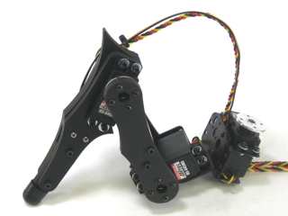
Image of completed Right (robot's right) leg. |
| |
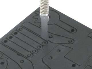
| Removing the parts from the panel
The PVC parts need to be carefully cut out of the panel. A thin, flat blade exacto knife will be very helpful when removing the parts. Simply cut through the tabs to remove the parts. |
Parts in the kit. |
| |
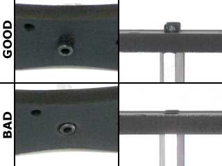
IMPORTANT!
DO NOT overtighten screws on the PVC parts! The PVC will compress and will become weaker as a result! |
Example image. |
| |
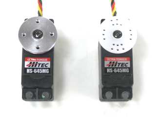
Preparation.
Remove the nylon servo horn from each servo and replace them with a metal servo horn. Be sure to keep it in the same orientation. |
Example image. |
|
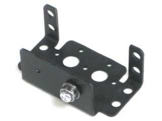
Figure 1. (Left Leg) |
Step
1.
Attach a ball bearing to a Multi-Purpose bracket as shown. See the diagram below for detailed information. Be sure the ball bearing's flange is near the bracket. Make three of each.
Figure 1-1.
|
.jpg)
Figure 1. (Right Leg) |
| |
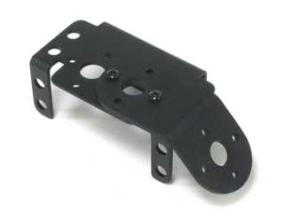
Figure 2. (Left Leg) |
Step 2.
Attach the long side of the 45° "L" connector bracket to a different Multi-Purpose bracket as shown, using two 2-56 x .250 screws and 2-56 nuts. Make three of each.
| 12 x |
12 x |
 |
 |
|
.jpg)
Figure 2. (Right Leg) |
| |
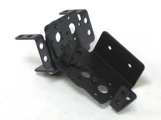
Figure 3. (Left Leg) |
Step
3.
Connect these two assemblies together as shown using two 2-56 x .250" screws and 2-56 nuts. You should have three of each.
| 12 x |
12 x |
|
|
|
.jpg)
Figure 3. (Right Leg) |
|
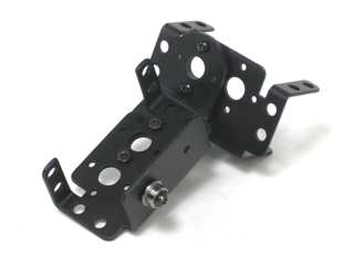
Figure 4. (Left Leg) |
Step 4.
Attach a ball bearing to the Multi-Purpose bracket as shown. See the diagram below for detailed information. Be sure the ball bearing's flange is near the bracket. Make three of each.
Figure 4-1.
|
.jpg)
Figure 4. (Right Leg) |
| |
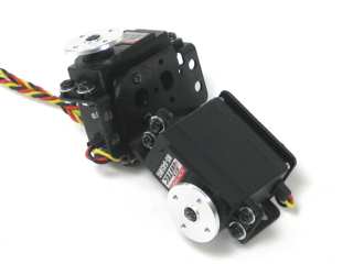
Figure 5. (Left Leg) |
Step
5.
Attach two servos to each assembly using the included 3mm hardware.
| 48 x |
|
 |
|
|
.jpg)
Figure 5. (Right Leg) |
| |
Step 6. (Optional leg switches)
The A-POD Leg Sensor kit comes with six servo extender cables with only one black connector. Cut a bit off the red wire and solder a 10k resistor to the end of each red wire. Then solder both the resistor lead and yellow wires to the lead labled "C". Solder the black wire to the lead marked "NO". These need to be soldered close to the body of the switch. When you're done you shouldn't need to use insulation. You will need to make up all six of these. |

Figure 6. |
| |
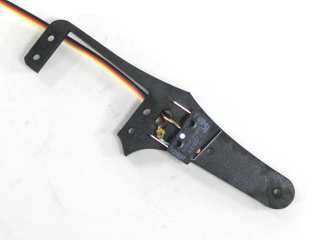
Figure 7. (Left Leg) |
Step
7. (Optional leg switches)
Slide the switch wire through the hole on a leg piece. The switch should end up on the "bad" side of the material. |
.jpg)
Figure 7. (Right Leg) |
|
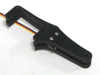
Figure 8. (Left Leg) |
Step
8. (Optional leg switches)
Attach the front of the tibia to the switch and rear piece using two 2-56 x .875" screws and two 2-56 nuts. Don't tighten these down all the way yet.
Figure 8-1.
|
.jpg)
Figure 8. (Right Leg) |
| |
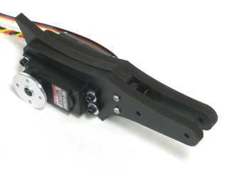
Figure 9. (Left Leg) |
Step
9.
Slide the middle piece of the leg in place and attach the servo using four 4-40 x 1.0" screws and 4-40 nuts. Do not tighten these down completely yet.
Figure 9-1.
|
.jpg)
Figure 9. (Right Leg) |
| |
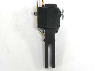
Figure 10. (Left Leg) |
Step
10.
Attach the plastic servo hinges to the back of the servos using the included pieces of double-sided foam tape. Remember to keep the bearing mount in-line with the servo horn. After this is in place, tighten down the all the screws on the leg assembly.
Figure 10-1.
|
.jpg)
Figure 10. (Right Leg) |
| |
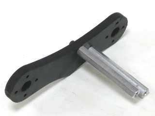
Figure 11. (Left Leg) |
Step
11.
Attach two hex standoffs to a femur piece using two 4-40 x .375" screws as shown. The standoffs should be on the "bad" side of the material. Make three for each side of the robot.
| 12 x |
|
 |
|
|
.jpg)
Figure 11. (Right Leg) |
|
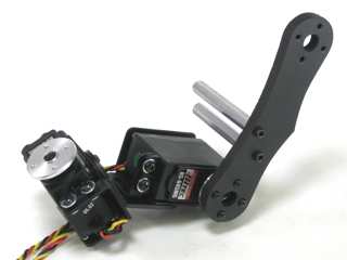
Figure 12. (Left Leg) |
Step
12.
Connect the femur to the servo as shown using four 2-56 x .375" screws. The standoffs should be near the servo as shown.
| 24 x |
|
 |
|
|
.jpg)
Figure 12. (Right Leg) |
| |
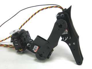
Figure 13. (Left Leg) |
Step
13.
Attach the tibia assembly to the femur as shown using four 2-56 x .375" screws.
| 4 x |
|
.GIF) |
|
|
.jpg)
Figure 13. (Right Leg) |
| |
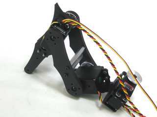
Figure 14. (Left Leg) |
Step
14.
Attach the rear panel of the tibia using two 4-40 x .375" screws.
| 2 x |
|
.GIF) |
|
|
.jpg)
Figure 14. (Right Leg) |
| |
Figure 15. (Left Leg) |
Step
15.
Install the sliding foot piece as shown, using two 4-40 x 1.0" hex head screws and nylon insert lock nuts. DO NOT tighten these down completely. This will cause the piece to not be able to slide and activate the switch.
| 12 x |
12 x |
 |
 |
|
.jpg)
Figure 15. (Right Leg) |
|
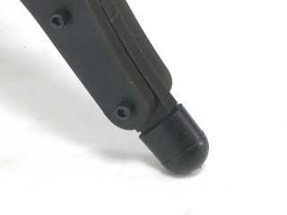
Figure 16. (Left Leg) |
Step
16.
Cut a rubber foot down to size and slide it over the over the end of each leg assembly, and you're finished! |
.jpg)
Figure 16. (Right Leg) |
| |
