The Complete T-Hex 4DoF Tutorial (Bot Board II)
| The Complete 4DOF T-HEX Tutorial
Updated 01/05/2011 This guide follows the T-HEX assembly guide. The purpose of this guide is to calibrate the servos and control the robot with a PS2 remote control. Hardware/Electronics: Software: |
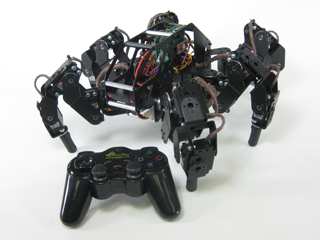 Image of 4DOF T-HEX. |
||||||||||||||||||||||||||||||||||||||||||||||||||||||||||||||||||||
|
|
|||||||||||||||||||||||||||||||||||||||||||||||||||||||||||||||||||||
| Step 1. SSC-32 Firmware Update. Place the robot on top of a CD spindle or similar to hold the legs off the ground. Download and install LynxTerm. Connect the SSC-32 to the serial port and apply power. The green LED should light and stay on until it receives a valid serial command. Please consult the serial troubleshooting guide if you have difficulties with this. |
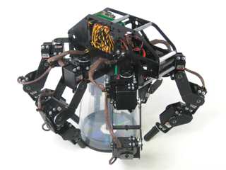 Figure 1. |
||||||||||||||||||||||||||||||||||||||||||||||||||||||||||||||||||||
| Step 2. Download the 2.04GP Beta firmware. Remove power from the SSC-32, and make sure the baud rate is set to 115.2k. Refer to the manual if you need more information regarding baud rate. Apply power to the SSC-32 again, make sure it's connected to the PC, and click on "Firmware" along the bottom of the LynxTerm screen. Click on "Open" and browse to the firmware file you just downloaded. Click on "Begin Update". |
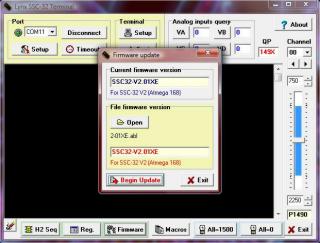 Figure 2. |
||||||||||||||||||||||||||||||||||||||||||||||||||||||||||||||||||||
| Step 3. When the firmware has been successfully updated, click "Ok" then "Exit". Now do the "ver" test: type "ver" into the terminal then press "Enter". You should see the proper firmware version returned. |
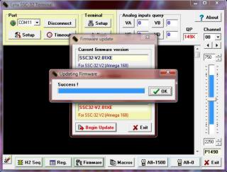 Figure 3. |
||||||||||||||||||||||||||||||||||||||||||||||||||||||||||||||||||||
Step 4. SSC-32 Registers. If the joints are off by more than 15° you may have made an error in assembly. To correct this, remove the center screw from the round servo horn, pull the servo horn off the servo, rotate until it's aligned, then reattach the servo horn. |
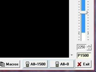 Figure 4. |
||||||||||||||||||||||||||||||||||||||||||||||||||||||||||||||||||||
| Step 5. From the main screen, click on "Reg" to open the Registers page. Click on "Default" to initialize default values. |
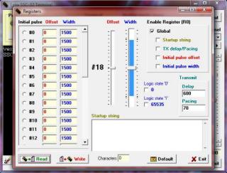 Figure 5. |
||||||||||||||||||||||||||||||||||||||||||||||||||||||||||||||||||||
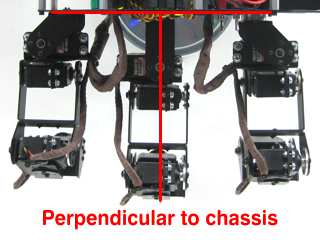
| Step 6. You need to adjust the robot's horizontal hip servos. Select servo #00, then adjust the "Offset" slider until the tibia is in perpendicular to the robot's chassis as shown. Do this for servos #00, 04, 08, 16, 20, 24. Note, the mouse's scrollwheel or keyboard's arrow keys can be used to make fine adjustments. |
|
||||||||||||||||||||||||||||||||||||||||||||||||||||||||||||||||||||
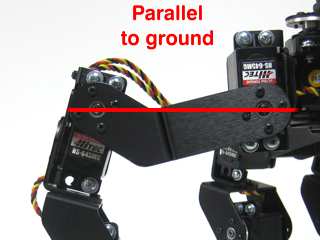
| Step 7. Now adjust the robot's first vertical hip servo. Select servo #01, then adjust the "Offset" slider until the robot's femur is parallel to the ground as shown. Do this for servos #01, 05, 09, 17, 21, 25. |
|
||||||||||||||||||||||||||||||||||||||||||||||||||||||||||||||||||||
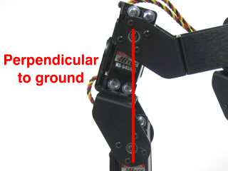
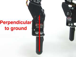
| Step 8. Now adjust the robot's second vertical hip servo. Select servo #02, then adjust the "Offset" slider until the robot's ankle servo is directly underneath the second servo pivot point. From the servo's pivot point to the foot's servo should be perpendicular to the ground as shown. Do this for servos #02, 06, 10, 18, 22, 26. |
|
||||||||||||||||||||||||||||||||||||||||||||||||||||||||||||||||||||
| Step 9. You need to adjust the robot's knee servos. Select servo #03, then adjust the "Offset" slider until the foot is parallel to the ground as shown. Do this for servos #03, 07, 11, 19, 23, 27. |
|
||||||||||||||||||||||||||||||||||||||||||||||||||||||||||||||||||||
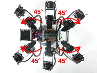
Step 10. Remove the center screws on the four corner hip servos (front right, front left, rear right, rear left), pull the servo horn off of the servo and rotate the leg outward 3 'clicks', or 45°. Replace the screws when you are finished. |
|
||||||||||||||||||||||||||||||||||||||||||||||||||||||||||||||||||||
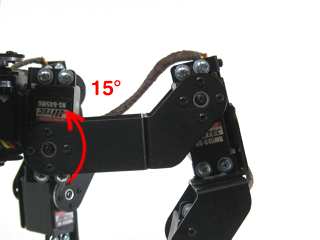
| Step 11. Using the same method, adjust each leg's first vertical servo upward one 'click', or 15°. The long 'C' bracket should now be parallel to the ground. |
|
||||||||||||||||||||||||||||||||||||||||||||||||||||||||||||||||||||
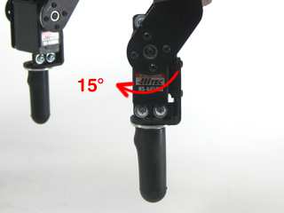
| Step 12. Also adjust each leg's knee inward one 'click' or 15°. |
|
||||||||||||||||||||||||||||||||||||||||||||||||||||||||||||||||||||
Step 13. Setting up the Bot Board II Remove the TX and RX jumpers from the lower-right corner of the SSC-32, and plug the unmodified end of the cable in. Yellow on TX, red on RX, and black on ground. See the schematic below step 14 for detailed information. |
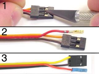 Figure 13. |
||||||||||||||||||||||||||||||||||||||||||||||||||||||||||||||||||||
Step 14. Make sure that the ABC buttons / LED jumpers are removed. Install the speaker enable jumper. Install your modified cable to I/O P10 and P11, where black is closest to the outside of the board and yellow is on the I/O pin. Consult the manual for the Bot Board II if needed. Note: Refer only to Figure 14-1 for PS2 cable connection information. The cable colors in the picture may be outdated. If your cable's colors do not match the diagram, you can find a complete listing of possible colors here.
|
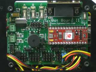 Figure 14-2. |
||||||||||||||||||||||||||||||||||||||||||||||||||||||||||||||||||||
Schematic.
|
|||||||||||||||||||||||||||||||||||||||||||||||||||||||||||||||||||||
| Step 15. Use some double-sided foam tape to secure the PS2 receiver to the robot's chassis as desired. Plug the receiver into the cable. We simply have ours resting in the chassis. |
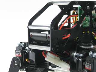 Figure 15. |
||||||||||||||||||||||||||||||||||||||||||||||||||||||||||||||||||||
| Step 16. Download the Program Download the latest version of BASIC Micro Studio and the 4DOF T-Hex code here. Install and run the application to allow programming the BASIC Atom Pro chip. Please consult the serial troubleshooting guide and the Basic Mirco Studio Programming Guide if you have difficulties with this. When you are finished programming the robot, you should hear a few short beeps, the legs will not snap to position until the START button on the PS2 remote is pressed. At this point, if you properly calibrated the servo offsets, the legs should be perfectly aligned. |
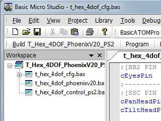 Figure 16. |
||||||||||||||||||||||||||||||||||||||||||||||||||||||||||||||||||||
| Step 17. Controlling the Robot If you hear a continuous beeping when you power the robot on, the PS2 controller is not connected to the Atom properly or is not functioning. You can test the controller with a Playstation 2 to verify that it is working.
This robot design was heavily inspired by the original T-Hex by KÃ¥re Halvorsen (Zenta on the forum). The Phoenix code was written by Jeroen Janssen (Xan on the forum). A big thanks to KÃ¥re and Jeroen! |
|
||||||||||||||||||||||||||||||||||||||||||||||||||||||||||||||||||||