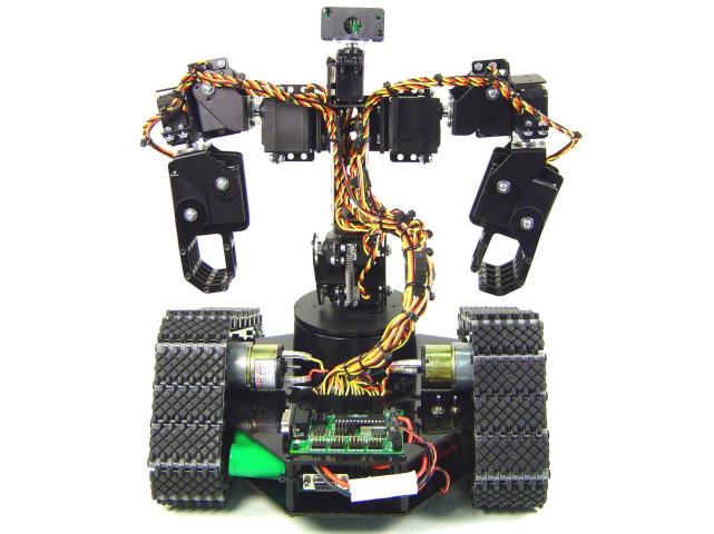
Johnny 5 Torso Assembly Guide
| Johnny 5 Torso Assembly Guide.
Updated 10/21/2009. Safety first! Wear eye protection and never touch a powered robot! Note: Loctite or thread locks can be used on the construction of the aluminum components. However, don't use them with Lexan, as they are not necessary and may cause damage. |
 Image of Johnny 5. |
||||||||
| Step 1. Prepare the base as in the base assembly guide. However, you will attach an ASB-04 Multi-Purpose bracket instead of the ASB-13. Use four 2-56 x .250 screws and 2-56 nuts.
|
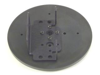 Figure 1. |
||||||||
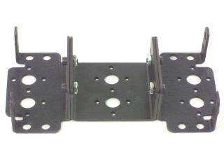
| Step 2. Attach two Short "C" brackets together as shown, using two 2-56 x .250 screws and 2-56 nuts.
|
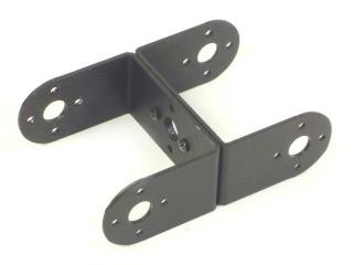 Figure 2. |
||||||||
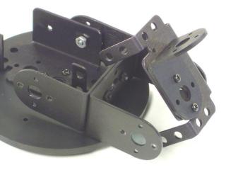
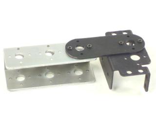
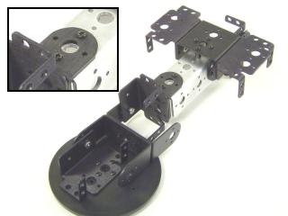
| Step 3. Attach one end of the Short "C" bracket assembly to the Multi-Purpose bracket as shown. See the diagram below for detailed information.
|
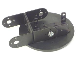 Figure 3-2. |
||||||||
| Step 4. Attach the other end of the Short "C" bracket assembly to a Multi-Purpose bracket as shown. See the diagram below for detailed information.
|
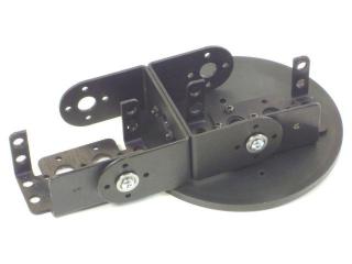 Figure 4-2. |
||||||||
| Step 5. Attach the "L" bracket to the Multi-Purpose bracket using two 2-56 x .250" screws and 2-56 nuts. Make sure the long edge of the "L" bracket connects to the Multi-Purpose bracket.
|
|
||||||||
| Step 6. Attach the Interconnect bracket to the 3" channel using two 2-56 x .250" screws and 2-56 nuts.
|
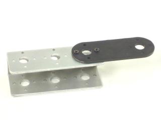 Figure 6. |
||||||||
| Step 7. Attach a Multi-Purpose bracket to the Interconnect bracket using two 2-56 x .250" screws and 2-56 nuts.
|
|
||||||||
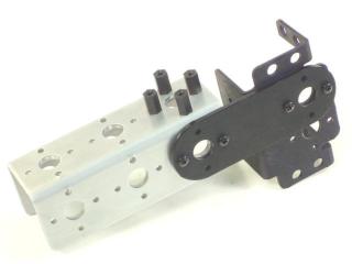
| Step 8. Thread a 2-56 nut onto four 2-56 x 1/4" screws. Pass these screws through the channel and thread the ends into the .313" hex spacers. The hex nut acts as a spacer.
|
|
||||||||
| Step 9. Attach two Multi-Purpose brackets to the Passive Hinge bracket as shown. Use four 4-40 x .250" hex socket head screws and four 4-40 nuts.
|
|
||||||||
| Step 10. Attach the chest assembly to the hex standoffs on the 3" channel as shown, using four 2-56 x .250" screws.
|
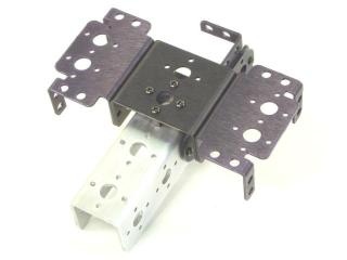 Figure 10. |
||||||||
| Step 11. Attach the "L" bracket to the 3" channel as shown, using two 2-56 x .250" screws.
|
|
||||||||
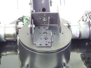
| Step 12. Install the base top. The hole pattern should line up as shown in Figure12, with one line pointing to the servo wire hole, and all of the lines pointing between the mounting tabs. Note, this top piece is manufactured to be a tight fit. You might have to press very hard. Attach the top with the servo horn screw. Plug the base servo into Channel 0 on the SSC-32. |
|
||||||||
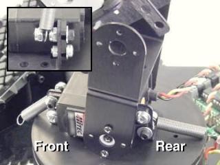
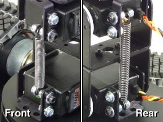
| Step 13. Install an HS-645 servo into the Multi-Purpose bracket as shown. Use two #2 x .250" tapping screws to attach the bracket to the servo horn. For all servo installations, you have the option to use the 3mm hardware or the nylon rivet fasteners. The 3mm hardware will make a more rigid assembly, but the nylon rivet fasteners are faster. You can use whichever method suits you. Follow Figure 13-1 to install two springs on the servo, as shown in Figure 13-2. Plug the bottom torso servo into Channel 1 on the SSC-32.
|
|
||||||||
| Step 14. Install an HS-645 servo into the Multi-Purpose bracket as shown. Use two #2 x .250" tapping screws to attach the bracket to the servo horn. Follow Figure 14-1 to install the other end of the springs on the servo, as shown in Figure 14-2. Plug the top torso servo into Channel 2 on the SSC-32.
|
|
||||||||
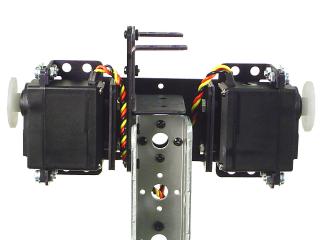
| Step 15. Install two HS-645 servos in the Multi-Purpose brackets in the shoulder positions as shown. Attach a 6" servo extender cable to each of the shoulder servos. Plug the robot's left shoulder servo into Channel 3 on the SSC-32, and plug the robot's right shoulder servo into Channel 8.
|
|
||||||||
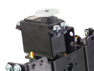
| Step 16. Install an HS-422 servo in the Multi-Purpose bracket in the head position as shown. Attach a 6" servo extender cable to the head servo. Plug the head servo into Channel 13 on the SSC-32.
|
|
||||||||
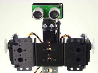
| Step 17. Install the Multi-Purpose Sensor Housing to the head servo, using two #2 x .250" tapping screws. You can attach a sensor as shown, but the sensor is not included in the Johnny 5 kit.
|
|
||||||||
| Step 18. Follow the assembly guide for the hand and arm. Attach the arms to the shoulder servos using four #2 x .250" tapping screws. Attach a 6" servo extender cable to each servo closest to the shoulder. Attach 12" extender cables to the other three servos in each arm. On the robot's left side, plug the shoulder (up/down) servo into Channel 4 on the SSC-32, the forearm (rotate) into Channel 5, the wrist into Channel 6, and the hand (open/close) into Channel 7. On the robot's right side, plug the shoulder (up/down) servo into Channel 9 on the SSC-32, the forearm (rotate) into Channel 10, the wrist into Channel 11, and the hand (open/close) into Channel 12. Route the servo wires through the aluminum channel as shown. |
|
||||||||
| Step 19. Plug the robot's left motor through the motor controller into Channel 14 on the SSC-32, and the right motor into Channel 15. This completes the mechanical assembly for Johnny 5. |
|
||||||||
| Servo Wires. Route the servo wires as shown, and straighten them up with wire ties. Remember to leave enough slack in the wires to allow the full range of motion!
|
|||||||||
| Wiring Diagram. Here is a supplemental image showing which SSC-32 channel each servo or motor should be plugged into.
|
|||||||||