Tri-Track Assembly Instructions v1.0
Last modified by Eric Nantel on 2023/01/30 15:32
| Tracked Vehicle Assembly Instructions Ver. 1.
Updated 12/20/2011 Safety first Wear eye protection and never touch a powered robot! Note: Do not use Loctite or thread locks on the assembly. They are not necessary and may cause damage to the Lexan. |
 Image of the chassis. |
||||||||||||||||||||||||||||||
| Lexan Preparation. The lexan pieces have a protective covering that needs to be removed before assembly. When the laser cuts, the covering melts into the cut edge which can make removal difficult. If you gently scrape the cut edge with a flat blade screwdriver, the covering can easily be lifted and peeled off. On smaller pieces the coverings can be more difficult to remove. If you have trouble you can gently scrape the cut edge, then use duct tape to lift the covering off. For further information on lexan, see this page. |
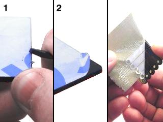 Lexan Preparation. |
||||||||||||||||||||||||||||||
| Step 1. Attach four 3" aluminum bars to the inside pair of lexan panels as shown. Use 4-40 x .375" hex screws.
|
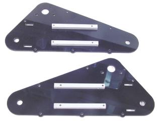 Figure 1. |
||||||||||||||||||||||||||||||
| Step 2. Attach 1.5" hex standoffs to the lexan panels as shown. Use 4-40 x .375" screws.
|
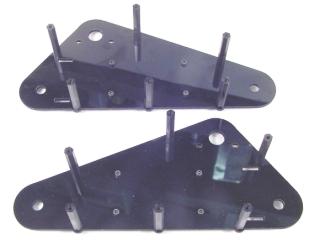 Figure 2. |
||||||||||||||||||||||||||||||
| Step 3. Attach the motors as shown, using four 3mm x 8mm screws. Make sure the motor shafts and the hex standoffs are on the same side of the lexan panels.
|
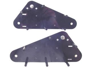 Figure 3. |
||||||||||||||||||||||||||||||
| Step 4. Install the hubs onto the motor shafts as shown. Align the hub to be flush with the end of the motor shaft. Tighten the set screw down firmly. |
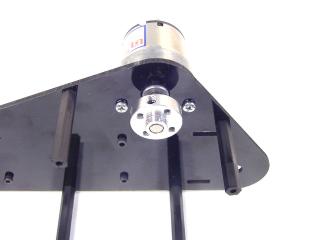 Figure 4. |
||||||||||||||||||||||||||||||
| Step 5. Install the sprockets onto the hubs as shown. Take care to make the teeth on the sprockets line up as shown! Use two 4-40 x .625" screws per side.
|
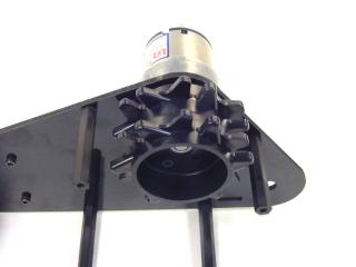 Figure 5. |
||||||||||||||||||||||||||||||
| Step 6. Prepare the idler sprockets. Install the two sprocket halves back-to-back on the long end of the idler hub. Take care to make the teeth on the sprockets line up as shown! Attach them with two 3mm x 8mm screws. Make four idler sprocket assemblies.
|
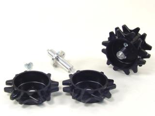 Figure 6-2. |
||||||||||||||||||||||||||||||
| Step 7. Attach ball bearings to the idler sprockets as directed in either Figure 7-1A or Figure 7-1B, depending on which version of the idler hub you have. Install the idler sprockets into the side panel as shown in Figure 7-2. Slide twelve nylon bushings over the nylon standoffs.
|
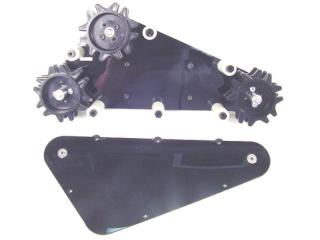 Figure 7-2. |
||||||||||||||||||||||||||||||
| Step 8. Install the outer lexan panels as shown to close up the assemblies. Use twelve 4-40 x .375" screws.
|
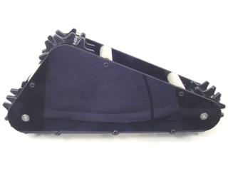 Figure 8. |
||||||||||||||||||||||||||||||
| Step 9. Wrap the 21-segment track assembly around the sprockets, push the axel in and secure with two nylon snap rivet fasteners. These parts are included with the track kit, not the chassis kit.
|
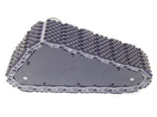 Figure 9. |
||||||||||||||||||||||||||||||
| Step 10. You should now have two assemblies that look something like this. |
 Figure 10. |
||||||||||||||||||||||||||||||
| Step 11. Attach 1.5" hex standoffs to the bottom panel as shown. Use 4-40 x .375" screws.
|
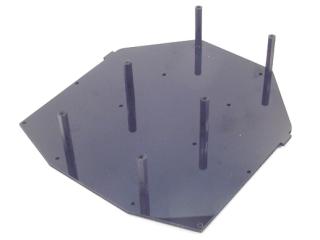 Figure 11. |
||||||||||||||||||||||||||||||
| Step 12. Attach the top panel as shown. Use six 4-40 x .375" screws.
|
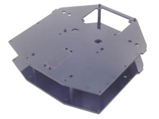 Figure 12. |
||||||||||||||||||||||||||||||
| Step 15. Attach the track assemblies to the chassis as shown. Use eight 4-40 x .375" screws.
|
Figure 15. |
||||||||||||||||||||||||||||||
| Step
16. Push the capacitor legs through the holes in the motor terminals. Bend the capacitor legs down onto the terminals as shown. |
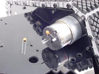 Figure 16. |
||||||||||||||||||||||||||||||
| Step
17. Push the motor wire connectors onto the motor terminals. Make sure to put the red wires on (+) and the yellow wires on (-). |
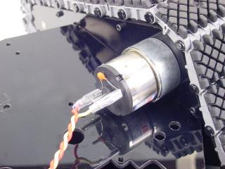 Figure 17. |
||||||||||||||||||||||||||||||
| Step
18. Install the wiring harness as shown. This switch will be for the 7.2vdc battery that powers the Sabertooth motor controller. Additional mounting holes allow adding separate power switches for accessories you add to the mobile platform, such as an arm, Johnny 5 torso, etc. |
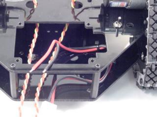 Figure 18. |
||||||||||||||||||||||||||||||
| Step
19. Refer to Table 19 for Sabertooth connection information. We've included the switch settings we used for Johnny 5 - you may need to use different settings for your application. You can find which direction to flip the switches on the card included with the Sabertooth. Route the motor wires through the holes in the chassis as shown! When the Sabertooth is properly connected and set up, use some double-sided foam tape to secure it inside the chassis.
|
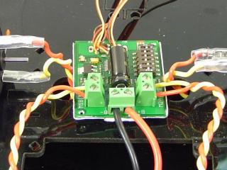 Figure 19. |
||||||||||||||||||||||||||||||
| Step
20. The Sabertooth has a battery elimination feature (BEC). This is useful when connecting the Sabertooth to an R/C receiver as it provides 5vdc at 500mA. This BEC can power the receiver itself and a couple of servos in low power applications, such as a pan-and-tilt. However, when more powerful servos are connected to the R/C receiver, you must disable the BEC and provide a separate battery to the R/C receiver and its servos. It is also necessary to disable the BEC if you are connecting the Sabertooth to an SSC-32. To disable the BEC, pull the red wire out of the black housings of the CH1 and CH2 wires as shown in Figure 21. Be sure to cover the exposed wire with heat shrink to prevent accidental short circuits! |
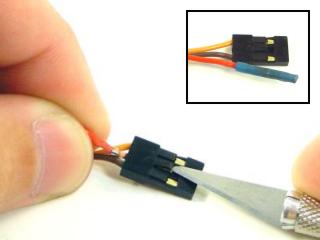 Figure 20. |
||||||||||||||||||||||||||||||
| Step
21. This wiring harness is not included in the Tri-Track Chassis kit. We are illustrating what is necessary to install an SSC-32 to control an arm, Johnny 5 torso, or other servo-based addition. This switch will be used for a 6vdc battery. |
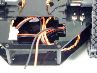 Figure 21. |
||||||||||||||||||||||||||||||
| Step
22. If you are using both an SSC-32 and a Bot Board, you will install them as shown in Figure 22. If you are only using the SSC-32, you will secure it with the four screws and standoffs. |
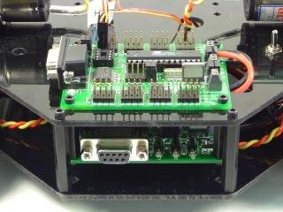 Figure 22. |
||||||||||||||||||||||||||||||
| Step
23. You can install the optional base rotate using the top screws from the standoffs. |
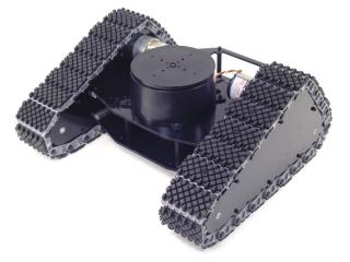 Figure 23. |
||||||||||||||||||||||||||||||