BRAT Biped SEQ Tutorial v1.06XE
| Biped
BRAT SEQ Tutorial.
Updated 09/20/2006. Safety first! Wear eye protection and never touch a powered robot! Software: |
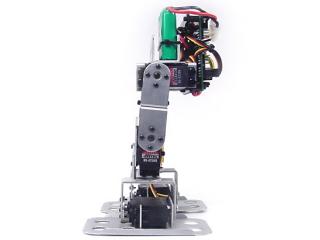
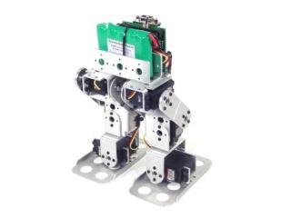 Image of Biped BRAT. |
||||||||||||||
|
I. BRAT Configuration |
|||||||||||||||
| Step
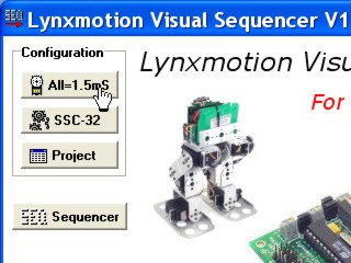
1. Install the SSC-32 Visual Sequencer. Read the Sequencer's manual. This tutorial is not meant to replace the manual! Connect the SSC-32 to the serial port and apply power. The green LED should light and stay on until it receives a valid serial command. Run the Visual Sequencer program. Step 2. |
|
||||||||||||||
| Step
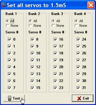
3. Click the "Test" button. |
|
||||||||||||||
| Step
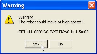
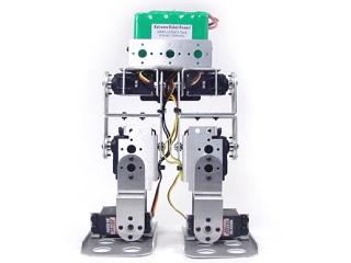
4. Place the robot in a position as close to neutral as possible. Click "Yes" and the robot should go to and hold the neutral position. Your robot should resemble figures 4-2 and 4-3. If the joints are off by more than 15° you may have made an error in assembly. To correct this, you remove the center screw from the round servo horn, pull the servo horn off the servo, rotate until it's aligned, then reattach the servo horn. When you are done, click on the "Stop" then "Exit" buttons. |
|
||||||||||||||
|
|
|
||||||||||||||
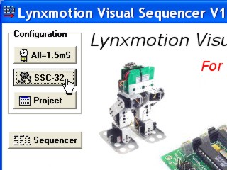
| Step
5. Click on "SSC-32" in the upper left corner. This process configures the software to the servos in your robotic assembly. To do this, the servos' neutral, min, and max positions are defined and the actual angles each joint can achieve are entered. Take time to do an accurate configuration! Your robot will only perform as well as the accuracy of the configuration file it's using. In other words, sloppy configuration will make a sloppy robot when sharing projects. |
|
||||||||||||||
| Step
6. Each servo you configure must first be enabled. You simply click on the Enable checkbox. You can move the servo by adjusting the slider bar. You will enable the servos one at a time as you configure them. |
|
||||||||||||||
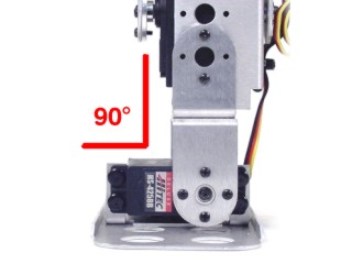
| Step
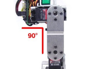
7. Channel 0 is for the BRAT's ankle on the right leg. Move the slider for servo 0 until the servo is at a 90° angle as shown. Note, the mouse's scrollwheel or keyboard's arrow keys can be used to make fine adjustments. |
|
||||||||||||||
| Step
8. Right click on the slider and select "Set position as neutral (0°)" from the menu. Note, you can see the actual servo pulse length in microseconds in the "Position" box on the left. This can be helpful to make a pulse offset table for experimenting with BASIC programming. |
|
||||||||||||||
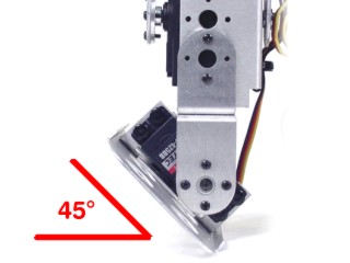
| Step
9. Move the slider for servo 0 until the servo is at a 45° angle as shown. Right click on the slider and select "Set position as min" from the menu as shown in Figure 9-2. Adjust the "Min Deg" box to say "-45°" as shown in Figure 9-3. |
|
||||||||||||||
|
|
|
||||||||||||||
| Step
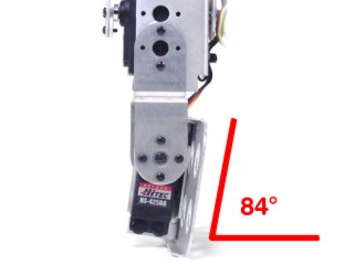
10. Move the slider for servo 0 until the servo is at an 84° angle as shown. Right click on the slider and select "Set position as max" from the menu as shown in Figure 10-2. Adjust the "Max Deg" box to say "84°" as shown in Figure 10-3. Move the slider back to 0° before going on to the next servo. |
|
||||||||||||||
|
|
|
||||||||||||||
| Step
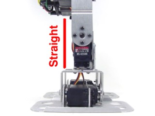
11. Channel 1 is for the BRAT's right knee. Adjust and set the neutral (0°) position with the knee straight as shown in Figure 11-1. Adjust and set the min and max positions as shown in Figure 11-2 and 11-3. Note, you do not have to change the angles because the knee can reach +/-90°. Move the slider back to 0° before going on to the next servo. |
|
||||||||||||||
|
|
|
||||||||||||||
| Step
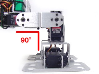
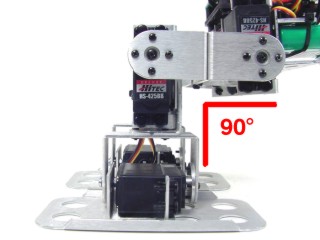
12. Channel 2 is for the BRAT's right hip. Adjust the hip as shown in Figure 12-1 and set the neutral (0°) position. Adjust the hip as in Figure 12-2 and set the minimum (-90°) position. Adjust the hip as in Figure 12-3 and set the maximum (45°) position. For clarity, the knees were bent in Figure 12-3. Move the slider back to 0° before going on to the next servo. |
|
||||||||||||||
|
|
|
||||||||||||||
| Step
13. The robot's right side is now configured. You can now configure the robot's left side. Click on the "Bank 3" button to gain access to channels 16-23. Channel 16 is the right ankle, 17 is the right knee, and 18 is the right hip. Configuring these channels is identical to configuring channels 0-2 with one exception: After you are done with the normal configuration, you must click on the "Reverse" checkbox for these three channels! Make sure all servos are set to 0° (home) and save your work. For this robot, "home" position is with all the servos set to their 0° position. However, any position you leave the sliders in when you save the configuration is how the robot will look when you start Sequencer. In other words, "home" position does not have to be the 0° position, that's just what we used. Save your work. The .cfg file will need to be loaded each time you run the program. If you only have one robot to set up, save over the "ConfigSSC32.cfg" file. However, if you plan on using the sequencer with more than one robot, then input a new file name, such as "BipedBRAT.cfg" It's important that you save these files in the install directory, default C:\Program Files\Sequencer_SSC-32\ |
|
||||||||||||||
| Step
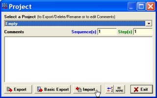
14. Now we're going to import a pre-made project. This will enable you to use other people's projects on your robot. Download this zip file. It contains several projects. Unzip it into the SEQ install directory. By default, it is C:\Program Files\Sequencer_SSC-32\ Click on "Project" in the upper left corner. |
|
||||||||||||||
| Step
15. Click on "Import," then select "biped6-long stride.csv" and click "Open," then "OK." Enter a project name or leave the default, then click "OK." You should see an "Import success" message. Click "Exit." |
|
||||||||||||||
| Step
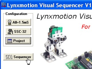
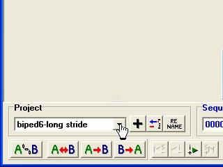
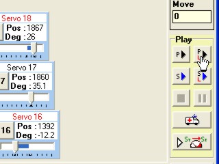
16. Now for some fun! Let's make that robot walk! Click on "Sequencer" as shown in Figure 16-1. From the drop down menu in the project section, select "biped6-long stride." In the Play menu, click on "Project Loop" as shown in Figure 16-3. Caution, the robot will start moving immediately. To stop the robot, click on the black "stop" or "pause" buttons. If everything went well, your robot should have walked across the table. If it appears that the legs are moving in the same positions, you may have forgotten to reverse the servos on the robot's left side. |
|
||||||||||||||
|
|
|
||||||||||||||
| Step
17. Refer to Table 17 for a list of the projects included in the zip file and a video link when available. After you're comfortable with playing projects, you can consult the Sequencer manual for more information on how to create your own. Remember to send us images and videos of your cool projects so we can publish them online! |
|||||||||||||||
|
II. Creating a Walking Sequence |
|||||||||||||||
| Step
1. Run the Sequencer program. Select the "empty" project from the Project drop down menu, and click on the black "+" to make a new project. Enter a name for your project. As we are making the robot walk, a name such as "BRAT-Walk" might be applicable. |
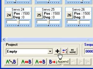 Figure 1. |
||||||||||||||
| Step
2. Now we're faced with an empty project and a screen full of servo blocks. To make the screen more manageable, click on "Swap" at the top. This will swap the selected servos with the unselected ones. Since no servos are unselected, this will clear the screen. Now just click on the servos that you need, which should be servos 0, 1, 2, 16, 17, and 18. |
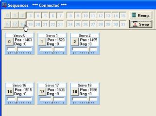 Figure 2. |
||||||||||||||
| Step
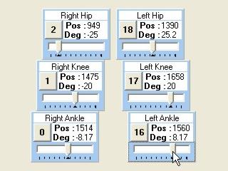
3. You can click and drag the servo boxes to arrange them so they resemble the robot's physical layout. |
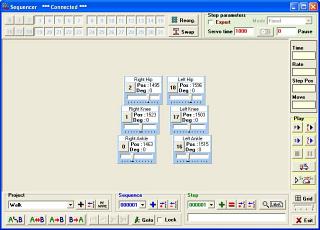 Figure 3. |
||||||||||||||
| Step
4. You can also name the servos by clicking on the number in the servo box. It will bring up the screen in Figure 4. In addition to naming the servo, you can change the color of the servo box. |
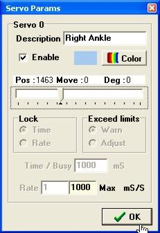 Figure 4. |
||||||||||||||
| Step
5. Now we're almost ready to make the robot walk. First, here's an outline of the walking sequence. The last two steps are just mirror images of the first two steps. |
|
||||||||||||||
| Step
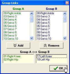
6. To make this project even easier, click on the "A  B"
button in the lower left corner. This screen allows you to link servos
together. Click on "Servo 1" on the left side and "Servo
17" on the right, then click "Add." Do the same with Servos
2 and 18. This will allow you to switch the positions of the right and
left legs with just a few clicks. B"
button in the lower left corner. This screen allows you to link servos
together. Click on "Servo 1" on the left side and "Servo
17" on the right, then click "Add." Do the same with Servos
2 and 18. This will allow you to switch the positions of the right and
left legs with just a few clicks. |
|
||||||||||||||
| Step
7. The first step in this walk is to get the robot into position to take a stride in the second step. Set your servos to the degrees shown in Table 7. They don't have to be exact; close will do. When you're done, click on the red "=" in the Step section to overwrite Step 1.
|
|
||||||||||||||
| Step
8. Now, click on "A<=>B" and deselect the "Selected step" check box and click OK. Then click the green "+" in the Step section to add the current position as a new step. |
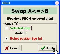 Figure 8. |
||||||||||||||
| Step
9. To shift the robot's weight, just use the sliders and switch the degrees for Servos 0 and 16. Click on the green "+" in the Step section when you're done to add this as a new step. |
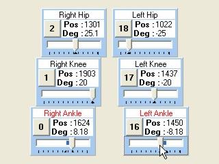 Figure 9. |
||||||||||||||
| Step
10. Now all you have to do is take another step! Click on the "A<=>B" button again, deselect "Selected step" if it isn't already, and click OK. Click on the green "+" in the Step section when you're done. |
Figure 10. |
||||||||||||||
| Step
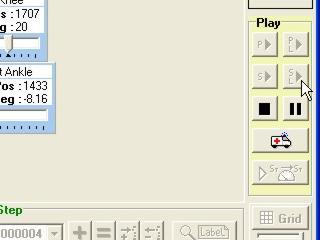
11. To test the walk sequence, click on the sequence loop button on the right side of the screen under "Play." You can stop or pause the walking sequence from the Play menu. If you were successful, the robot should be walking now. If the robot doesn't walk in a straight line, try increasing the ankle degrees so that more weight is shifted. |
|
||||||||||||||
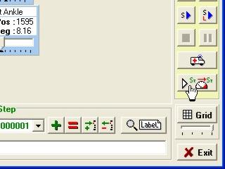
| Step
12. To adjust the biped's walking speed, you can use the "Advanced Play" feature. Click on the Advanced Play button on the right side of the screen. |
|
||||||||||||||
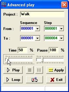
| Step
13. By moving the Time slider, you will adjust the speed of all the servos in the project to a percentage of the normal speed. 100% is the project's normal speed. Moving the slider below 100% causes the robot to move faster, while above 100% slows the robot down. Click on the Loop button to test your new speed. You can tweak the speed while the robot is moving to get it perfect. If you click on the Apply button, the new speed will be applied to the project. |
|
||||||||||||||