BRAT Biped Assembly Guide
| Biped
BRAT Assembly Guide
Updated May 2015 Safety first! Wear eye protection and never touch a powered robot! This guide applies to the following versions of the BRAT biped:
Important! To assemble the BRAT robot, construct a right leg (following the pictures on the right), and a left leg (by following the pictures on the left)! Keep in mind that the pictures marked "Right Leg" are the robot's right leg. After the legs are constructed, the images will no longer be split. |
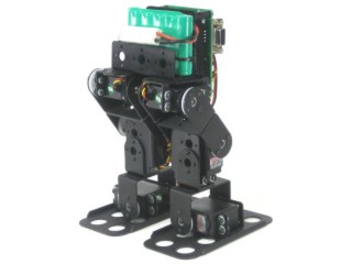 Image of completed robot. |
|||||
|
|
||||||
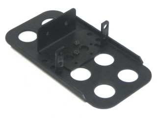 Figure 1. (Left Leg) |
Step 1.
|
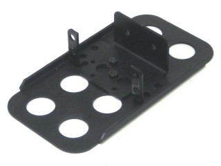 Figure 1. (Right Leg) |
||||
 Figure 2. (Left Leg) |
Step 2.
|
 Figure 2. (Right Leg) |
||||
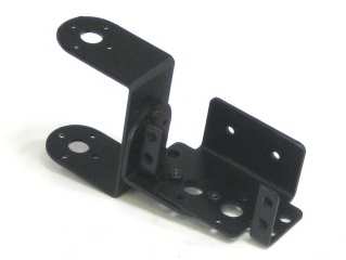 Figure 3. (Left Leg) |
Step 3.
|
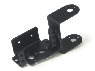 Figure 3. (Right Leg) |
||||
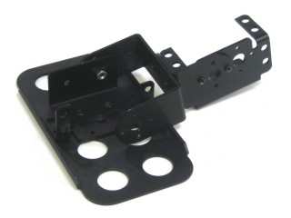 Figure 4. (Left Leg) |
Step 4.
|
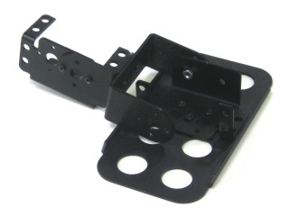 Figure 4. (Right Leg) |
||||
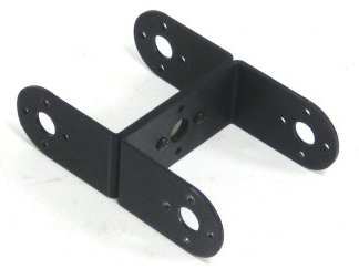 Figure 5. (Left Leg) |
Step 5.
|
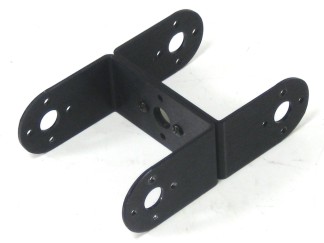 Figure 5. (Right Leg) |
||||
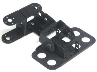 Figure 6. (Left Leg) |
Step 6.
|
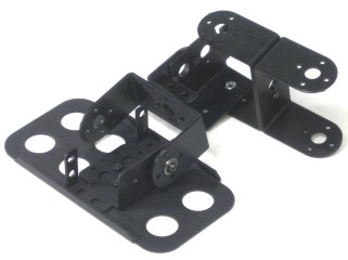 Figure 6. (Right Leg) |
||||
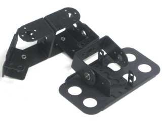 Figure 7. (Left Leg) |
Step 7.
|
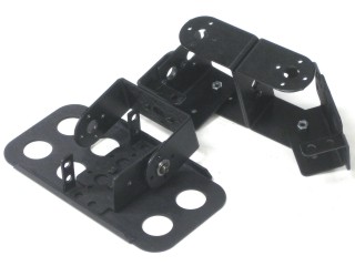 Figure 7. (Right Leg) |
||||
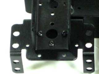 Figure 8. (Left Leg) |
Step 8.
|
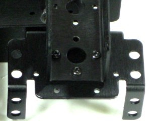 Figure 8. (Right Leg) |
||||
|
|
||||||
|
Step 9. |
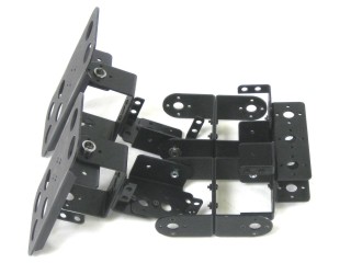 Figure 9. |
|||||||||||||||||||||||
|
Step 10.
|
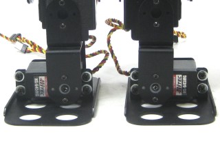 Figure 10. |
|||||||||||||||||||||||
|
Step 11.
|
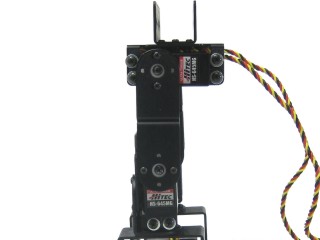 Figure 11. |
|||||||||||||||||||||||
|
Step 12a (SSC-32 / SSC-32U). Attach the 3/4" standoffs to the electronics carrier using four 4-40 x 1/4" hex socket head cap screws.
|
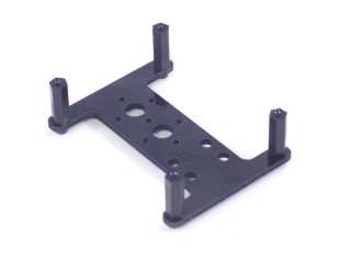 Figure 12a. |
|||||||||||||||||||||||
| Step
12b (Optional PS2 Receiver). Note that the optional PS2 receiver is only compatible with the BotBoarduino and Bot Board 2. If you have the SSC-32 or SSC-32U, or do not plan to use the PS2, follow step 12a. Follow this step if you have the BotBoarduino or Bot Board 2 AND plan to mount the optional PS2 receiver plate / PS2 receiver. Attach the 1/2" standoffs to the electronics carrier using four 4-40 x 1/4" hex socket head cap screws. Note that some images in the steps below will show the 3/4" spacers mounted to the carrier; your version however will have the 1/2" spacers.
|
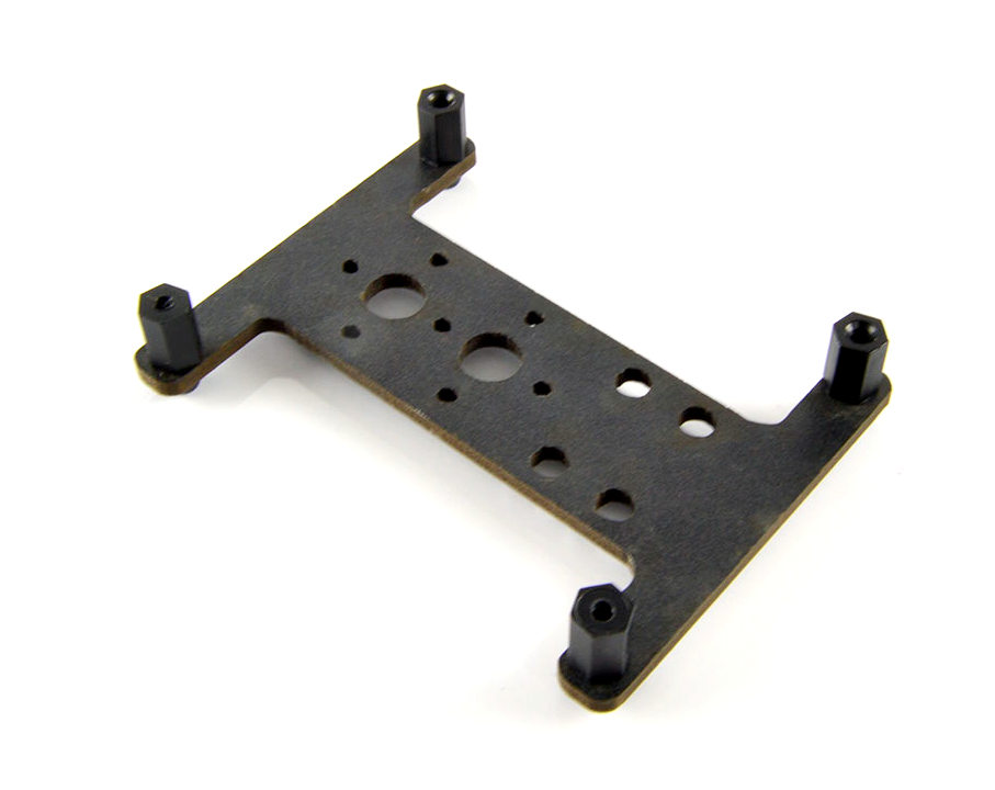 Figure 12b. |
|||||||||||||||||||||||
|
Step 13.
|
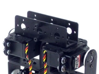 Figure 13. |
|||||||||||||||||||||||
|
Step 14.
|
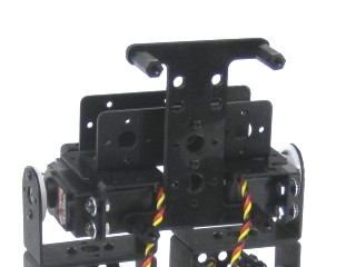 Figure 14. |
|||||||||||||||||||||||
|
Step 15. Make sure that the ankle servo is positioned as shown when securing the wires to ensure the full range of motion is available. |
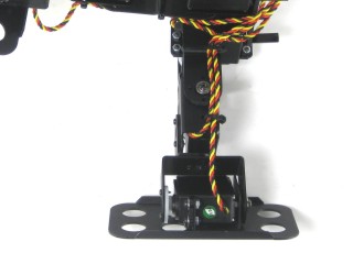 Figure 15. |
|||||||||||||||||||||||
| |
||||||||||||||||||||||||
|
Step 16. |
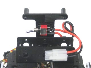 Figure 16. |
|||||||||||||||||||||||
|
Step 17a (SSC-32 /
SSC-32U / Bot Board 2 ). It is best to orient the board
with the screw terminas at the bottom of the robot. If using a Bot Board II, go ahead and install the BASIC Atom Pro 28 chip as well in the orientation shown below. Note that if you are using the optional PS2 mounting plate, you should follow that guide and use 1" M/F standoffs instead.
|
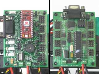 Figure 17 (Bot Board 2, SSC-32, SSC-32U). |
|||||||||||||||||||||||
|
Step 17b (BotBoarduino). Note that if you are using the
optional PS2 mounting plate, you should follow that setup and use 1"
M/F standoffs instead of the 4-40 x 0.25" screws below.
At this point you can also mount the PS2 receiver to the Lexan PS2
mounting plate using the four screws provided. This involves removing
the existing screws on the receiver and using the screws provided to
mount it to the Lexan.
|
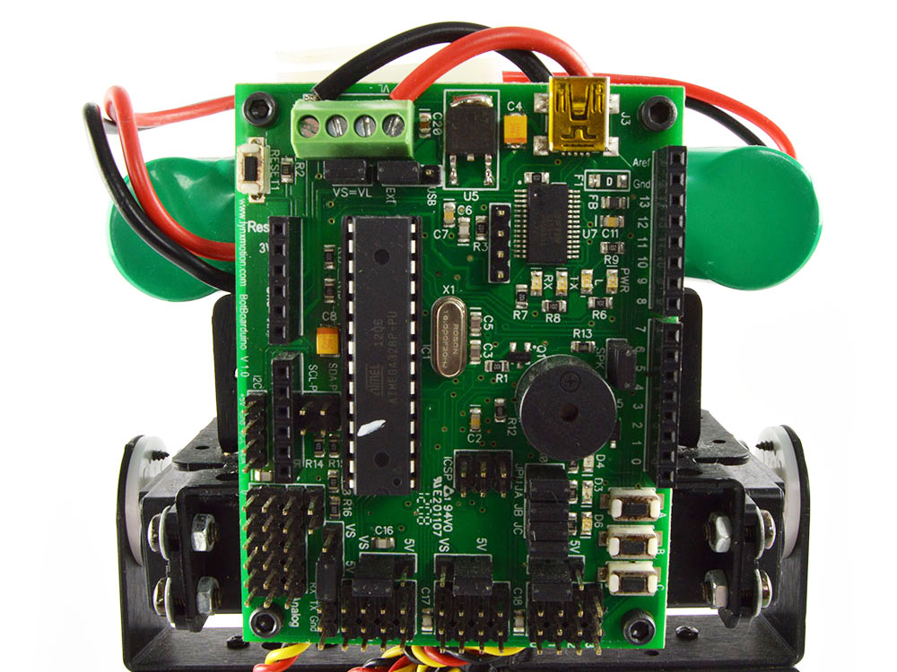 Figure 17b (BotBoarduino). |
|||||||||||||||||||||||
|
Step 18. In preparation for connecting the power wires, here are some general guidelines when inserting multistrand wires into screw terminals. Use a ~2mm wide flat blade screw driver. Rotate the screw both directions looking into the end of the terminal. When you see it open up (moving downwards), keep turning until it is open completely. Wrap / twist the wires by hand to ensure they are aligned as in Figure 6. Be sure that the wires are fully inserted into the terminals and that no stray wires touch each other between terminals as this is a short and can cause the battery to discharge rapidly, causing heat and possibly fire. DOUBLE CHECK THE RED AND BLACK WIRE CONNECTED TO THE SCREW TERMINALS - the red wire should go to (+) and the black wire to (-), if they are reversed, the servos and the board will be damaged. |
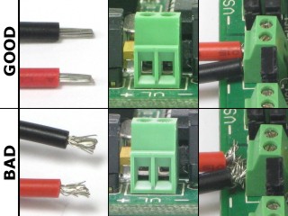 Figure 18 (Top shows open, bottom shows closed). |
|||||||||||||||||||||||
|
Step 19a (SSC-32 / SSC-32U / Bot Board 2). Connect the battery wiring harness to VS1 on the SSC-32 / SSC-32U or VS on the Bot Board II. Note, red is (+) and black is (-).For the SSC-32 / 32U, leave the VL = VS jumper in place (as well as the VS1 = VS2 jumpers). Connect the servos to their appropriate I/O channels on the board using the table below, and make sure to check your work. Please note that on table 19a, pin 10 is NOT a typo; pin 9 is used on the Bot Board II for the speaker.
|
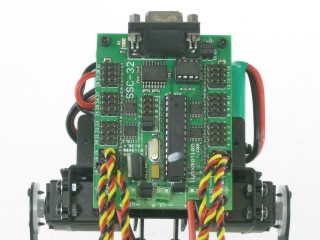 Figure 19a (SSC-32 as example). |
|||||||||||||||||||||||
|
Step 19b (BotBoarduino). Connect the wiring harness to
EITHER VS or VL on the BotBoarduino. Leave the VL = VS jumper in place.
Note, red is (+)
and black is (-). Connect the servos to their
appropriate I/O channels on the board using the table below, and make
sure to
check your work.
|
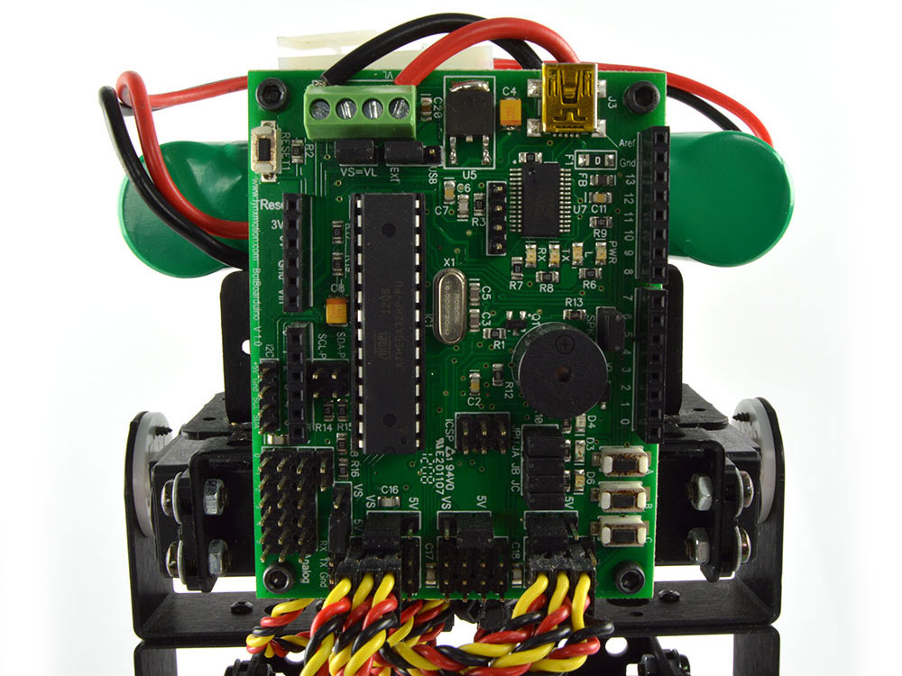 Figure 19b (BotBoarduino). |
|||||||||||||||||||||||
|
Step 20a. If you have the 6V, 1600mAh NiMh battery, note that it fits nicely inside the U-Channel. You can then secure it in place with zip-ties. |
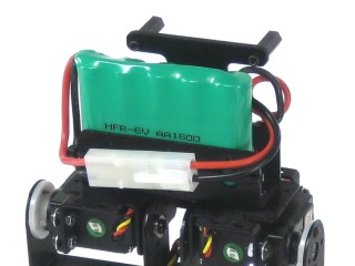 Figure 20a (1600mAh Battery). |
|||||||||||||||||||||||
|
Step 20b. |
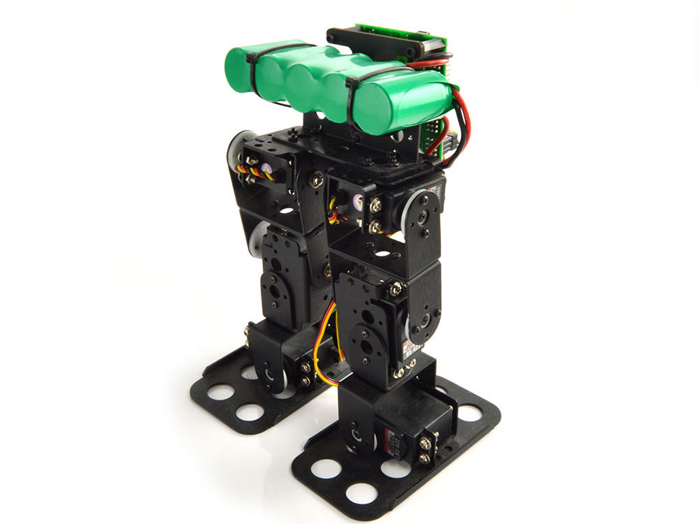 Figure 20b (2800mAh Battery). |
|||||||||||||||||||||||
|
Step 20. For controlling this robot with
the SSC-32U and FlowBotics Studio, please install and open FlowBotics
Studio and follow the instructions. For those using a Bot Board II, you can now move on to the Autonomous, Water-Bottle Kicking, or PS2 tutorial. If you have a BotBoarduino, you can move on to the BRAT + BotBoarduino + PS2 tutorial. Note that there is currently no sample code available for autonomous behavior using the BotBoarduino. |
Figure 20. |
|||||||||||||||||||||||
| Step
21 (Optional PS2 Receiver). If you have the optional PS2 receiver and mounting plate, figure 21 shows you what the final robot will look like. You can mount the PS2 Lexan + receiver assembly using four 4-40 x 1/4" screws. Note again that the PS2 receiver only works with the Bot Board 2 or BotBoarduino versions of the BRAT kits. |
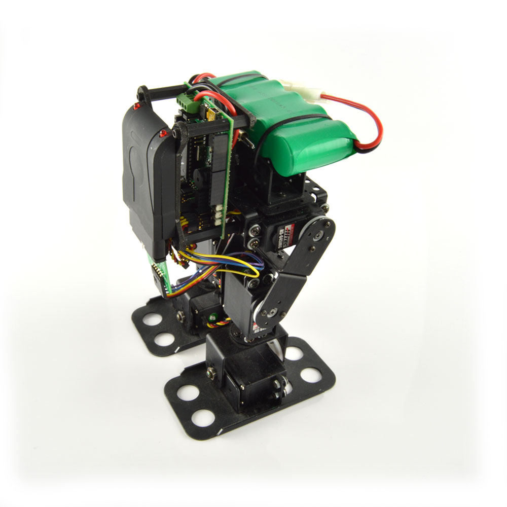 Figure 21. |
|||||||||||||||||||||||