Humanoid Biped Hand "A" Assembly Guide
Last modified by Eric Nantel on 2023/01/23 14:34
| Humanoid Biped Hand Assembly Guide.
Updated 12/21/2011 Safety first! Wear eye protection and never touch a powered robot! Note: This assembly guide covers the assembly of one arm and hand for the robot's right side. For the robot's left side, you will need to repeat these steps, making a mirror image of the arm and hand. |
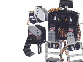 Image of Humanoid Biped with Hand. |
||||
| Lexan Preparation. The lexan pieces have a protective covering that needs to be removed before assembly. When the laser cuts, the covering melts into the cut edge which can make removal difficult. If you gently scrape the cut edge with a flat blade screwdriver, the covering can easily be lifted and peeled off. On smaller pieces the coverings can be more difficult to remove. If you have trouble you can gently scrape the cut edge, then use duct tape to lift the covering off. For further information on lexan, see this page. |
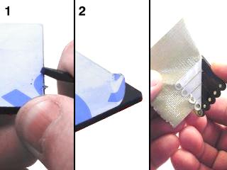 Lexan Preparation. |
||||
| Step 1. Attach two of the multi-purpose servo brackets as shown, using two 2-56 x .250" screws and 2-56 nuts.
|
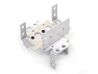 Figure 1. |
||||
| Step 2. Connect the offset "C" bracket to a multi-purpose bracket as shown. See figure 2-1 for detailed information.
|
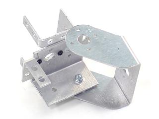 Figure 2-2. |
||||
| Step 3. Attach two servos as shown, using snap rivet fasteners and #2 tapping screws. For the Johnny 5 kit, use HS-645 servos here.
|
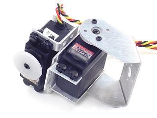 Figure 3. |
||||
| Step 4. Thread a 3/8" nylon spacer onto each of four 1.5" threaded rods. Follow this by a lexan finger panel, then another 3/8" spacer. Add a finger panel to either end as shown. |
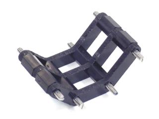 Figure 4. |
||||
| Step 5. Attach 3/8" nylon spacers at the ends of the threaded rod pieces as shown. Make sure you keep everything tight. |
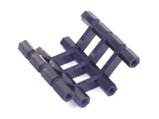 Figure 5. |
||||
| Step 6. Attach the long finger panels as shown, using eight 1/4" screws.
|
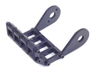 Figure 6. |
||||
| Step 7. Attach three 3/4" hex standoffs to the hand servo panel as shown, using three 1/4" screws.
|
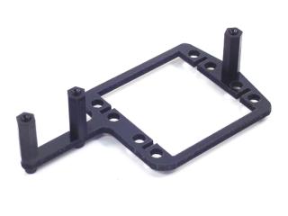 Figure 7. |
||||
| Step 8. Use eight snap rivet fasteners to hold two servos in place as shown. Note the orientation of the servos. For the Johnny 5 kit, use HS-475 servos in the position above the "thumb", and HS-422 servos for the "fingers".
|
 Figure 8. |
||||
| Step 9. Attach the second hand servo panel as shown. Use three 1/4" screws.
|
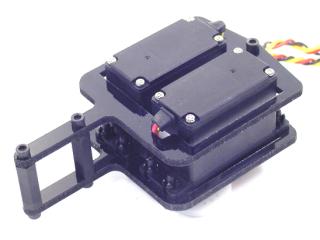 Figure 9. |
||||
| Step 10. Firmly attach the servo hinges to the servos as shown. Make sure you line up the hole with the servo horn. |
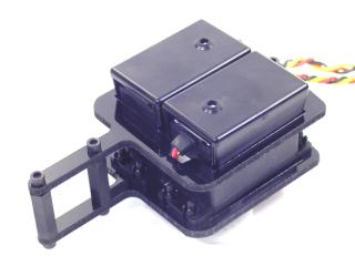 Figure 10. |
||||
| Step 11. Finish the hand by connecting the fingers to the servo as shown. Use the ball bearing hardware and four #2 tapping screws. Note, position the ball bearing so that the flange is outside the lexan.
|
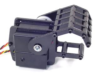 Figure 11. |
||||
| Step 12. When you want to attach the hand to a biped, use an offset bracket as shown. Note, position the ball bearing so that the flange is outside the bracket. To attach the arm to the biped torso, simply use two #2 tapping screws to attach the offset bracket to the torso servo.
|
Figure 12. |
||||