The Complete Hexapod 2 Tutorial
| The Complete Hexapod 2 Tutorial. Updated 01/26/2007
Hardware: Software: - Wiring Schematic (wd001.gif) - Wiring Schematic (h2l56wd.gif) Goal: |
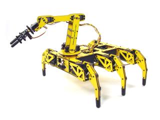
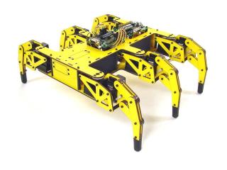 Image of Hexapod 2. |
||||||||||||||||||||||||||||||||||||||||||||||||||||||||||||||||||||||||||||||||||||||||||||||||||||||
|
|
|||||||||||||||||||||||||||||||||||||||||||||||||||||||||||||||||||||||||||||||||||||||||||||||||||||||
| Step 1. Install the Bot Board and SSC-32 onto the top of the robot as shown. |
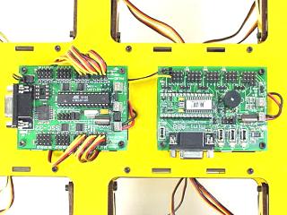 Figure 1. |
||||||||||||||||||||||||||||||||||||||||||||||||||||||||||||||||||||||||||||||||||||||||||||||||||||||
| Step 2. Connect power wires for the servos as illustrated. Click on Figure 2 for a larger, printable version. Install VS1 = VS2, VL = VS1, TX and RX, and both Baud jumpers for these tests. This will set the Baud rate to 115.2k and allow DB9 communications. Consult the SSC-32 user manual for more detailed information. |
 Figure 2. |
||||||||||||||||||||||||||||||||||||||||||||||||||||||||||||||||||||||||||||||||||||||||||||||||||||||
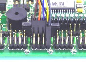
| Step 3. Connect the servos to their appropriate I/O channels. See Table 1 and consult the SSC-32 users manual. Double check your work. The header pins are close and numerous.
|
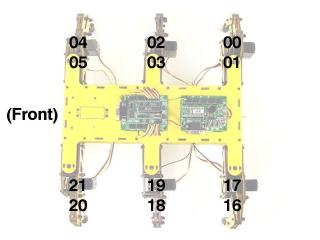 Figure 3. |
||||||||||||||||||||||||||||||||||||||||||||||||||||||||||||||||||||||||||||||||||||||||||||||||||||||
| Step 4a. Connect the serial data cable to the PC's serial port. This can be recognized by having 9 pins that stick out. Step 4b. Note, you can also use an IOGear USB-to-Serial adaptor. |
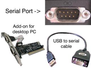 Figure 4. |
||||||||||||||||||||||||||||||||||||||||||||||||||||||||||||||||||||||||||||||||||||||||||||||||||||||
| Step 5. Install and run the LynxTerm on your PC. This program uses your computer's serial port to "talk" to the SSC-32. We will use it to quickly test your hexapod robot. This tool can also be extremely useful if you want to write a program for your favorite microcontroller to talk to the SSC-32 directly. Choose the COM Port for your computer from the drop down menu in the upper left corner. Note, if you notice the text going below the bottom of the box, it may be necessary to change the font settings and / or change the number of rows on screen under the Terminal Setup. Click in the black text box and type "ver". If everything is working correctly, you should receive a response such as "SSC32-1.03XE". |
|
||||||||||||||||||||||||||||||||||||||||||||||||||||||||||||||||||||||||||||||||||||||||||||||||||||||
| Step 6. Click on the Sequencer button in the lower left corner. Click "All = 1500" and notice the hexapod legs hold position. If the robot was constructed properly, the legs will be horizontal and perpendicular to the body. Now would be a good time to double check the H2 mechanical leg alignment. If your robot does not have mechanical alignment, then use the Offset tool under Servo Quick Test. Select the servo on the Hexapod diagram and adjust the offset slider to fine-tune the leg alignment. Do this for all twelve servos. When completed, click on Config to display the configuration data. Ignore the first four lines, as they do not pertain to the offset command. The lines starting with "#0PO" can be cut and pasted into the serout command in the programs included with this tutorial. Do a search for "Servo Offset" in the supplied programs and follow the instructions. |
|
||||||||||||||||||||||||||||||||||||||||||||||||||||||||||||||||||||||||||||||||||||||||||||||||||||||
| Step 7. The values for the L* and R* textboxes will control the positions the legs are moved to in the sequence. You can fine-tune these values to your mechanical leg arrangement with the same Servo Quick Test. Just adjust the position slider instead of the offset slider.
|
 Figure 7. |
||||||||||||||||||||||||||||||||||||||||||||||||||||||||||||||||||||||||||||||||||||||||||||||||||||||
| Step 8. Now to make the robot walk forward. Adjust the XL and XR sliders to 100%. Note that HT=1500uS (1.5 seconds). Set the XS slider to ~50% and notice that the stride takes 3 seconds. Adjust the HT slider to 1000 and notice that the stride now takes 2 seconds. You have complete control over all aspects of the tripod gait. Adjust either XL or XR lower to do gradual turns. Setting XL and XR to opposite directions will cause the robot to turn in place. Reverse values of XL and XR will cause the robot to walk backwards. Moving a slider is the same as typing from the terminal or sending the command from a microcontroller. For example, moving XS to 50% is the same as sending "XS50". Once the commands are sent, the robot will continue to walk until it receives XS = 0. If you are using a host microcontroller to send commands, it will be free to do any timing-intensive tasks without worrying about any of the walking process. |
|
||||||||||||||||||||||||||||||||||||||||||||||||||||||||||||||||||||||||||||||||||||||||||||||||||||||
| Step 9. For the do-it-yourselfers, the program to the right will set up and initiate walking on the robot. It will be necessary to remove the TX and RX jumpers, install the data cable to the Bot Board, and configure the Baud rate jumpers for 38.4k. Refer to the schematic in Figure 12. To change speed and direction just alter the XL, XR, XS values. The robot will immediately begin walking in the speed and direction commanded. We have several fully functional programs to choose from below. |
|
||||||||||||||||||||||||||||||||||||||||||||||||||||||||||||||||||||||||||||||||||||||||||||||||||||||
| Step 10. The following steps refer to several programs that offer complete control of all aspects of the hexapod gait sequence through a wireless PS2 controller. Install and run the BASIC Atom IDE to allow programming the chip.
|
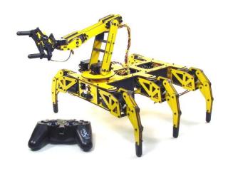 Figure 10. |
||||||||||||||||||||||||||||||||||||||||||||||||||||||||||||||||||||||||||||||||||||||||||||||||||||||
| Step 11. Wire your robot as illustrated in the wiring diagram to the right. Click on Figure 11 for a larger, printable version. The Sharp GP2D12 is not required, but offers crash protection if installed. You can use 7.2vdc battery for the best performance, however, if you're installing an L5 or L6 arm 6.0vdc is recommended. This is due to the micro servo on the gripper. For increased runtime, you can power the logic of the Bot Board and SSC-32 from a 9v battery. Just remember to remove the VS=VL jumpers on both boards. Don't forget to install the speaker enable jumper. This will provide audible feedback when using the controller with the provided programs. Install the PS2 receiver module and put fresh batteries in your controller. When you run the program, you should hear some beeps that will continue until the game controller is recognized. Press the Analog button and the legs should hold position. |
|
||||||||||||||||||||||||||||||||||||||||||||||||||||||||||||||||||||||||||||||||||||||||||||||||||||||
| Step 12. Install the Playstation 2 cable as illustrated in Figure 12-1 and 12-2.
|
|
||||||||||||||||||||||||||||||||||||||||||||||||||||||||||||||||||||||||||||||||||||||||||||||||||||||
| Step 13. Controlling the motion of the hexapod is handled in two ways. Make sure the controller is in Analog mode. Mode 1 (default) uses a differential or tank mode, where the right joystick controls the right legs, and the left joystick controls the left legs. Mode 2 allows control of the direction of walking with the right joystick, while Left and Right on the D-Pad adjusts speed. Pressing R3 swaps between control modes. Initially, in either mode the joystick positions will allow a max of 100% XS speed. Pressing D-Pad Left lowers the max in 5% increments, and D-Pad Right increases the max in 5% increments up to 200% Both modes offer additional control of leg trajectory for the alternating tripod gait. This refers to the vertical and horizontal motion that the foot goes through during the walking gait. Pressing /\, O (default), X, or [] changes how the foot is lifted in relation to the stride motion. Control the max vertical height with the R1/R2 buttons. Control the max low position (H2 body ride height) with the L1/L2 buttons. This can also be done with the D-Pad Up and Down buttons with a faster response. If the robot is driven toward an obstacle, after a threshold is reached the forward joystick position is ignored. However, you can still reverse direction. The controller will also vibrate proportionally in relation to the distance from the obstacle. The Sharp sensor can be enabled or disabled with the Start button. |
|
||||||||||||||||||||||||||||||||||||||||||||||||||||||||||||||||||||||||||||||||||||||||||||||||||||||
| Step 14. The Select button switches between Hexapod and Arm control. - Move X and Y (Up/Down, To/Away) with the Left joystick. |
|
||||||||||||||||||||||||||||||||||||||||||||||||||||||||||||||||||||||||||||||||||||||||||||||||||||||
|
|
|
||||||||||||||||||||||||||||||||||||||||||||||||||||||||||||||||||||||||||||||||||||||||||||||||||||||
| Step 15. The following autonomous-behavior program requires the addition of three Sharp GP2D12 sensors, connected as follows: A to D channel 0 sensor: on front left side, facing right. A to D channel 1 sensor: on front right side, facing left. A to D channel 2 sensor: on rear, facing behind the robot.
|
Figure 15. |
||||||||||||||||||||||||||||||||||||||||||||||||||||||||||||||||||||||||||||||||||||||||||||||||||||||