
3DoF MEGA Leg Assembly Instructions v1.0
Last modified by Eric Nantel on 2023/01/26 09:30
|
3 DOF MEGA Leg Assembly Instructions v1.0.
Updated 10/30/2012. Safety first! Wear eye protection and never touch a powered robot! Note: Do not use Loctite or thread locks on the assembly. They are not necessary and may cause damage to Lexan. |
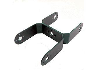
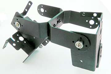
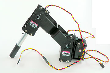 Image of completed 3DOF Mega leg. |
||||
|
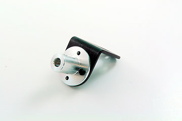
Step 1. Attach the ball bearing that comes with the chassis kit to the Multi-Purpose bracket as shown. If you purchased the leg pair separately (i.e no chassis or body kit), you will not have this bearing and can skip this step. Note that a ball bearing is strongly suggested for supporting the leg. See the diagram below for detailed information.
|
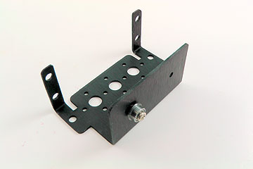 Figure 1-2. |
||||
| Step 2. Attach the Multi-Purpose bracket from step 1 to the other multipurpose bracket exactly as shown, using two 2-56 x .250 screws and 2-56 nuts.
|
 Figure 2. |
||||
| Step 3. In a separate assembly, attach two "C" brackets together, using two 2-56 x .250 screws and 2-56 nuts.
|
|
||||
| Step
4. Attach the "C" bracket assembly from step 3 to the Multi-Purpose bracket assembly from step 2 as shown. See the diagram below for detailed information.
|
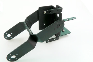 Figure 4-2. |
||||
| Step 5. Attach a Tubing Connector Hub to an "L" bracket as shown, using two 2-56 x .250 screws and 2-56 nuts.
|
|
||||
| Step 6. Attach the other side of the "L" connector bracket to the Multi-Purpose bracket as shown, using two 2-56 x .250 screws and 2-56 nuts.
|
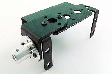 Figure 6. |
||||
| Step 7. Attach the Multi-Purpose bracket from step 6 to the "C" bracket assembly from step 3 as shown, using the ball bearing. See the diagram below for detailed information.
|
|
||||
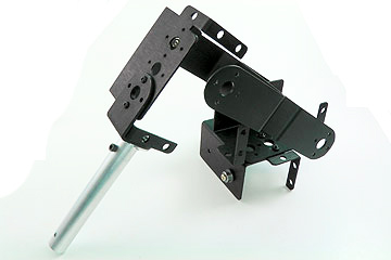
| Step 8. Connect a 3.375" tube to the hub using a 4-40 x .250" screw.
|
|
||||
| Step 9. Attach a rubber foot to the end of the tube. |
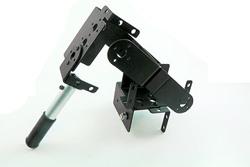 Figure 9-2. |
||||
|
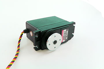
Step 10. Remove the plastic horn from all three servos and install the aluminum servo horn as shown. Note that the angle between the servo horn and the spline is very important. Use the SSC-32 or a servo positioner to position the servo at 90 degrees (1500us pulse). Refer to this tutorial: http://www.lynxmotion.com/images/html/build046.htm Note: If you position the plastic servo horn parallel to the length of the servo (as it is shipped from Hitec), it should be properly centered. Note that the holes on the aluminum servo horn should be parallel and perpendicular to the servo (not at some weird angle). |
|
||||
| Step 11. Install the servos as shown, using the included 3mm servo mounting hardware.
|
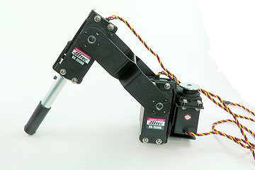 Figure 11. |
||||
| Step 12. Connect the 6" servo extension cable to the knee servo. Do not use tie wraps yet. |
Figure 12. |
||||
You can now move on to the body assembly instructions.